Apparatus for manufacturing ultrafine fiber and method for manufacturing ultrafine fiber

A technology of ultra-fine fiber and manufacturing equipment, applied in fiber processing, stretch spinning, melt spinning, etc., can solve the problems of poor productivity and uniformity, achieve high productivity, reduce production, and reduce resin blocks.

Inactive Publication Date: 2020-02-11
JXTJ NIPPON OIL & ENERGY CORP
View PDF5 Cites 0 Cited by
  • Summary
  • Abstract
  • Description
  • Claims
  • Application Information

AI Technical Summary

Problems solved by technology

In addition, Patent Document 2 proposes a method for producing nanofibers in which the problems of poor productivity and uniformity, which were the problems in the technology of Patent Document 1 above, are improved by vibration spinning of multifilaments.

Method used


Image

  • Apparatus for manufacturing ultrafine fiber and method for manufacturing ultrafine fiber
  • Apparatus for manufacturing ultrafine fiber and method for manufacturing ultrafine fiber
  • Apparatus for manufacturing ultrafine fiber and method for manufacturing ultrafine fiber

Examples


no. 1 approach

[0046] The present invention relates to a production method and production apparatus for producing ultrafine fibers having a fiber diameter (diameter) of 10 nm to 1 μm, preferably 30 nm to 800 nm.

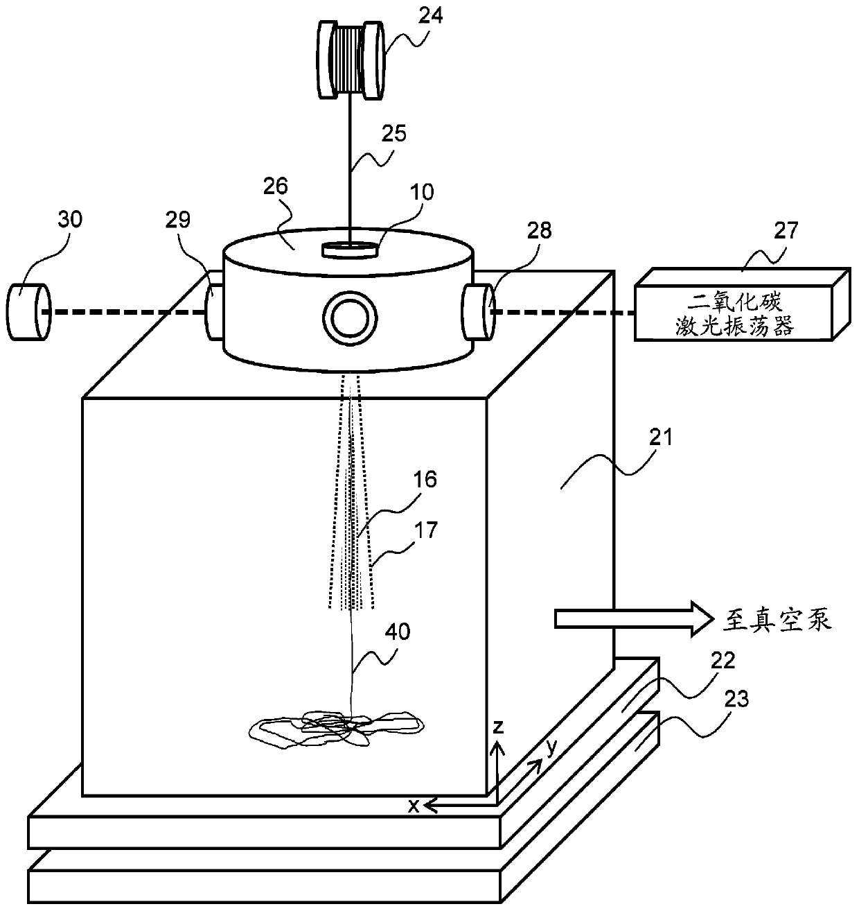
[0047] figure 1A schematic configuration diagram showing a so-called carbon dioxide laser ultrasonic stretching apparatus, which is an ultrafine fiber manufacturing apparatus according to the first embodiment of the present invention. This device manufactures superfine fiber (nanofiber) 40 in drawing chamber 21, and drawing chamber 21 is arranged on the movable stage 22 that can move respectively on x, y, z direction, and this movable stage 22 is arranged on fixed stage 23 superior. The fibrils (monofilament or multifilament) 25 wound on the fiber supply reel 24 are introduced from the inlet of the nozzle 10 serving as the fiber supply hole to the outlet. The fibrils 25 can be applied as long as they are polymer materials (thermoplastic polymer materials) that are melted by heat,...

no. 2 approach

[0076] Image 6 It is a schematic perspective view of the manufacturing apparatus of the ultrafine fiber concerning 2nd Embodiment of this invention. In the third configuration example of the nozzle described above, a speed adjustment mechanism 32 is provided to control the flow speed of the second stretched air flow 17 . In contrast, in the second embodiment, the flow rate of the second stretched air flow 17 is controlled using the speed controller 50 , the flow rate control device (control device) 51 , and the flow rate sensor (air flow sensor) 52 .

[0077] That is, a hollow annular speed adjustment chamber 53 is provided to cover the second introduction port 20 of the nozzle 10 , and air is supplied from the speed controller 50 to the speed adjustment chamber 53 through the pipe 54 . The speed controller 50 is under the control of the flow control device 51, based on the air volume or flow velocity detected by the air flow sensor 52, so that the flow velocity of the secon...

Deformed example 1

[0080] In addition, in the second embodiment, the flow rate control of the second stretched air flow 17 is performed by feedback control. However, it is also possible to configure, for example, a speed controller with a scale without the flow control device 51 or the flow sensor 52, and to control the flow rate manually while the operator visually checks the scale.


PUM

PropertyMeasurementUnit
diameteraaaaaaaaaa

Abstract

This apparatus for manufacturing ultrafine fiber comprises a nozzle (10), a laser irradiation unit (26), and a drawing chamber (21). The nozzle (10) comprises an inlet for supplying raw fibers (25), afirst spray outlet, communicating with the inlet, for delivering the raw fibers and spraying a first drawing gas stream (16) for drawing the raw fibers, and second spray outlets, disposed around thefirst spray outlet, for spraying a second drawing gas stream (17). The nozzle (10) is installed on the laser irradiation unit (26), and the raw fibers (25) delivered from the first spray nozzle are irradiated and melted by a laser. In the drawing chamber (21), the molten raw fibers (25) are drawn using the first drawing gas stream (16) and the second drawing gas stream (17) sprayed from the nozzle(10).

Description

technical field [0001] The present invention relates to a manufacturing device and method for ultrafine fibers, and is particularly suitable for nanofibers based on a laser stretching method in which fibrils are melted by laser and fibers are stretched by stretching air jets ejected from nozzles. spinning. Background technique [0002] Patent Document 1 describes a method for producing nanofibers using a laser drawing method. In addition, Patent Document 2 proposes a method for producing nanofibers in which the problems of poor productivity and uniformity, which were problems in the technique of Patent Document 1 above, are improved by vibration spinning of multifilaments. In this Patent Document 2, by supplying and vibrating multifilaments to a nozzle, nanofibers can be produced with high productivity from the viewpoint of forming multiple nanofibers. In addition, since a plurality of nanofibers are generated from one hole (nozzle) and randomly blow-molded by vibration, i...

Claims


Application Information

Patent Timeline
Patent Type & Authority Applications(China)
IPC IPC(8): D02J1/22
CPCD01D1/04D01D5/0985D01D5/14D02J1/22D01D5/08D02J1/224D02J13/00
Inventor 市林拓熊谷吉弘
Owner JXTJ NIPPON OIL & ENERGY CORP
Why Eureka
Try Eureka