A continuous heat storage system based on photothermal moving bed

A technology of heat storage system and moving bed, applied in the field of continuous heat storage system, can solve the problems of poor mass transfer and heat transfer performance, complex heat storage system, etc., and achieve the effect of solving agglomeration and continuous operation reliability.

Inactive Publication Date: 2021-03-23
HARBIN INST OF TECH
View PDF11 Cites 0 Cited by
  • Summary
  • Abstract
  • Description
  • Claims
  • Application Information

AI Technical Summary

Problems solved by technology

[0005] The purpose of the present invention is to propose a continuous heat storage system based on photothermal moving bed for the problems of material agglomeration, poor mass and heat transfer performance, and complex heat storage system in traditional hydrated salt adsorption heat storage reactors.

Method used


Image

  • A continuous heat storage system based on photothermal moving bed
  • A continuous heat storage system based on photothermal moving bed
  • A continuous heat storage system based on photothermal moving bed

Examples


specific Embodiment approach 1

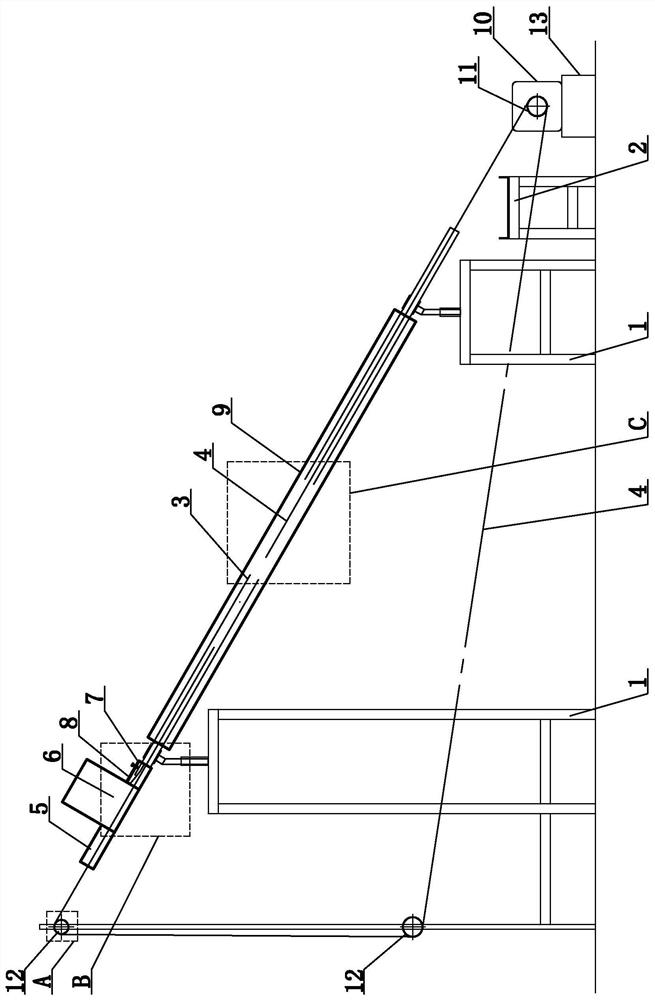
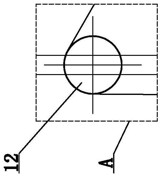
[0021] DETAILED DESCRIPTION Figure 1 - Figure 4 As shown in the present embodiment, a continuous heat storage system based on a photothermal moving bed comprises an automatic feed apparatus, a photothermal reactor, a transmission system, a material collecting device 2, a support frame 1, and a heat storage material. The discharge end of the automatic feed apparatus is connected to the feed end of the inner tube 3 of the photosensitive reactor, the photothermal reactor supports and tilt in the support frame 1, and the discharge end of the photothermal reactor is low. In the feed end, the material collecting device 2 is disposed below the discharge end of the photothermal reactor (for collecting a heat storage material that is free to fall after the discharge end of the photothermal reactor), the transmission system The chain 4 is pulled into the automatic feed apparatus and a photothermal reactor, and the heat storage material is added to the automatic feed apparatus, and the chain...

specific Embodiment approach 2

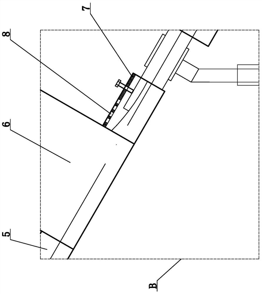
[0022] Detailed Embodiment 2: figure 1 , image 3 As shown, the present embodiment is a further description of the specific embodiment, the automatic feed device comprising a front conduit 5, a silo 6, and a rear conduit 7; the bottom of the front and rear side walls of the silo 6 are provided with Through hole, the through hole 6 front side is in communication with the front conduit 5 rear end, the through-hole of the rear side wall of the silo 6 communicates with the front end of the rear catheter 7, and a plurality of exhaust pipes are provided in front of the front part of the back pipe 7. The hole 8, the silo 6 tilt setting, the inclination angle of the silo 6 is the same as the photothermal reactor, and the angle of inclination between the front and rear side walls of the silo 6 and the horizontal plane is acute (facilitating the heat storage material to fall to the front and rear conduction) The heat storage material is added by the silo 6.

[0023] The front conduit 5 mai...

specific Embodiment approach 3

[0025] Specific Embodiment 3: If figure 1 , Figure 4 As shown, the present embodiment is further illustrated for the second embodiment, the photothermal reactor (the core component of the heat storage process) is a double-layer tube structure that is shared by the inner tube 3 and the outer tube 9. The outer tube 9 is a glass tube (having a high light permeability), and the outer wall of the inner tube 3 is provided with a selective absorbent coating (having high efficiency light absorbing ability, and the received light energy is efficiently converted to thermal energy, while Have a very low emissivity to reduce the radiant heat loss), and the inner tube 3 is formed between the inner tube 9 (preventing the inner tube 3 wall facing ambient heat dissipation), and the outer end of the inner tube is extended out of the outer tube 9. External; the chain 4 carries the heat storage material into the inner tube 3 (the heat storage material of the outer wall surface of the inner tube 3 ...


PUM


Abstract

The invention relates to a continuous type heat storage system based on a photo-thermal moving bed and belongs to the field of solar heat storage. The discharging end of an automatic feeding device isconnected with the feeding end of an inner pipe of a photo-thermal reactor, the photo-thermal reactor is supported by a supporting frame and is arranged in an inclined mode, the discharging end of the photo-thermal reactor is lower than the feeding end of the photo-thermal reactor, a material collecting device is arranged below the discharging end of the photo-thermal reactor, a chain in a transmission system penetrates into the automatic feeding device and the photo-thermal reactor, and heat storage materials are put into the automatic feeding device and driven by the chain in the transmission system to enter the photo-thermal reactor and then fall into the material collecting device through a discharging port of the photo-thermal reactor. According to the continuous type heat storage system, complex heat transmission parts do not need to be arranged in the photo-thermal and heat storage process, sunlight is directly absorbed to carry out photo-thermal conversion, and the heat is stored in the adsorbing type heat storage materials. Moisture desorption and heat storage are achieved by erecting a moving bed system, the problems of clustering and wall sticking of high-water-contentadsorbents are effectively solved through transmission of the chain, and the system is capable of running continuously and good in reliability.

Description

Technical field [0001] The present invention belongs to the field of solar thermal storage, and more particularly to a continuous reservoir system based on a photothermal moving bed. Background technique [0002] my country's solar energy resources are very rich, and the annual radiation exceeds 5000mJ / m 2 Area accounts for more than 96% land area. Bottlenecks such as solar energy and other bottlenecks are intermittent and instability of energy sources, which results in mismatches of the heat fever side and the demand side, while the heat storage technology is an effective way to solve this problem. Since the chemical heat storage has a high energy density, there is no need for adiabatic protection, and the storage cycle is long, and it is preferable to carry out solar heat storage. [0003] Hydrate salt adsorption heat storage has high heat storage densities, and the reaction temperature range (20 to 150 ° C) matches building heating, and is increasingly concerned about the ec...

Claims


Application Information

Patent Timeline
Patent Type & Authority Patents(China)
IPC IPC(8): F24S60/00F24S70/225
CPCF24S60/00F24S70/225Y02E10/40
Inventor 魏思雨苏彦麟李俊峰韩瑞周伟高继慧秦裕琨
Owner HARBIN INST OF TECH
Why Eureka
Try Eureka