
Compensation device and compensation control method used in wireless energy transmission system

A wireless energy transmission and compensation device technology, which is applied to output power conversion devices, circuit devices, and conversion devices without intermediate conversion to AC, and can solve problems such as affecting energy transmission efficiency, heating, and increasing the size of implanted devices. To achieve the effect of simple control structure, less circuit components, and simple implementation

Active Publication Date: 2021-02-12
SHENZHEN GRADUATE SCHOOL TSINGHUA UNIV
View PDF14 Cites 0 Cited by
  • Summary
  • Abstract
  • Description
  • Claims
  • Application Information

AI Technical Summary

Problems solved by technology

These methods have corresponding disadvantages. For example, adding a voltage regulator chip at the receiving end will increase the volume of the implanted device and energy loss will cause additional heat, which should be avoided as much as possible; the power control at the transmitting end needs to be added. Adjustable DC-DC chip will greatly affect the energy transmission efficiency

Method used


Image

  • Compensation device and compensation control method used in wireless energy transmission system
  • Compensation device and compensation control method used in wireless energy transmission system
  • Compensation device and compensation control method used in wireless energy transmission system

Examples


Embodiment Construction

[0031] Embodiments of the present invention will be described in detail below. It should be emphasized that the following description is only exemplary and not intended to limit the scope of the invention and its application.

[0032] In the description of this specification, references to the terms "one embodiment," "some embodiments," "preferred embodiments," "examples," "specific examples," or "some examples" are intended to mean A specific feature, structure, material, or characteristic described by an embodiment or example is included in at least one embodiment or example of the present invention. In this specification, the schematic representations of the above terms are not necessarily directed to the same embodiment or example. Furthermore, the described specific features, structures, materials or characteristics may be combined in any suitable manner in any one or more embodiments or examples. The terms "first" and "second" are used for descriptive purposes only, an...


PUM


Abstract

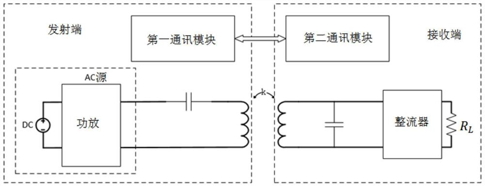
A compensation device and a compensation control method used in a wireless energy transmission system. The wireless energy transmission system includes an energy transmission circuit at a sending end and a receiving end, wherein the energy transmission circuit at the sending end includes an LC resonant circuit, and the compensation device includes an LCL compensation network, a voltage The feedback loop and the control circuit, the LCL compensation network includes a first inductance, a second inductance and an adjustable capacitor, the first inductance and the second inductance are connected in series with the LC resonant circuit, the adjustable capacitor is connected in parallel with the LC resonant circuit, and the adjustable capacitor One end is connected between the first inductance and the second inductance, the voltage feedback loop feeds back the output voltage state of the receiving end to the control circuit, the control circuit controls and adjusts the capacitance of the adjustable capacitor according to the output voltage state, and dynamically controls it through the LCL compensation network output voltage, so that the output voltage is stable within the set voltage range. The invention requires few circuit elements at the receiving end of the system, has simple control structure and high efficiency.

Description

technical field [0001] The present invention relates to wireless energy transmission technology, in particular to a compensation device and a compensation control method used in a wireless energy transmission system. Background technique [0002] Wireless energy transfer technology is very important. For implantable medical devices, wireless charging technology is smaller, safer, more convenient and reliable than built-in batteries and percutaneous wired interconnections. Existing wireless charging technologies are mostly based on electromagnetic fields, ultrasonic waves, optical connections, or capacitive coupling. Among them, electromagnetic induction energy transmission is an electromagnetic field technology, and the transmission loss of magnetic field in the human body medium is small, so it has higher energy transmission efficiency and lower heat dissipation. Therefore, inductive energy transmission is more suitable for implantable medical devices, and has higher stab...

Claims


Application Information

Patent Timeline
Patent Type & Authority Patents(China)
IPC IPC(8): H02J50/12H02M3/07
CPCH02M3/073H02J50/12H02M3/077
Inventor 唐仙赵一霖王志华
Owner SHENZHEN GRADUATE SCHOOL TSINGHUA UNIV
Learn More