Engineering vehicle

A technology for engineering vehicles and frames, which is applied to vehicle components, control devices, transportation and packaging, etc., to achieve the effects of overall weight reduction, high transmission efficiency, and low energy consumption

Pending Publication Date: 2020-02-25
TRANF TECH XIAMEN CO LTD
View PDF0 Cites 4 Cited by
  • Summary
  • Abstract
  • Description
  • Claims
  • Application Information

AI Technical Summary

Problems solved by technology

[0005] To solve this problem, the existing methods are mostly vehicle exhaust treatment, engine optimization design to improve the combustion effect, or road cleaning technologies such as watering and dust reduction; however, these solutions all reduce exhaust pollution to a certain extent, and cannot fundamentally solve the problem of vehicle exhaust.

Method used


Image

  • Engineering vehicle
  • Engineering vehicle
  • Engineering vehicle

Examples


Embodiment 1

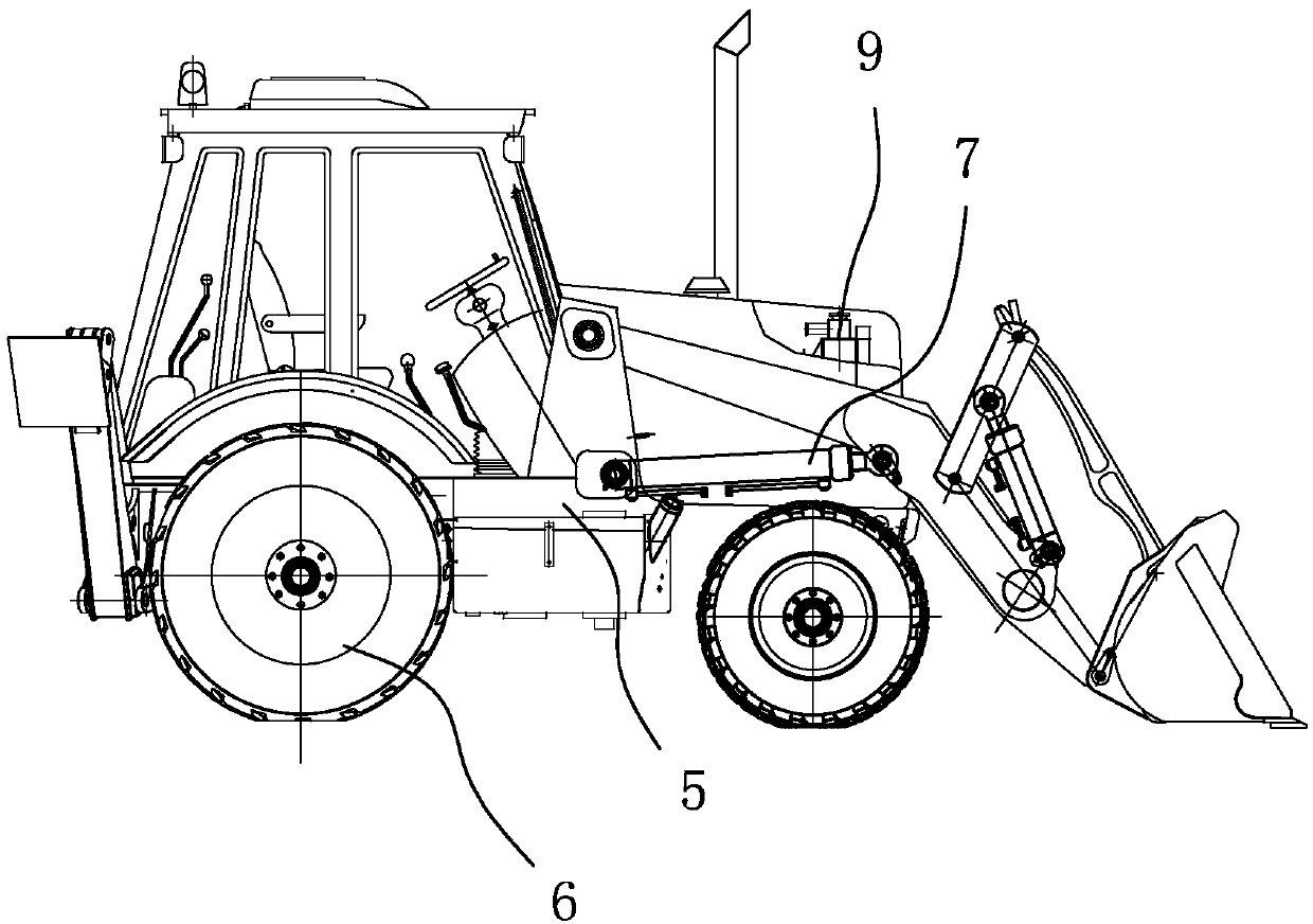
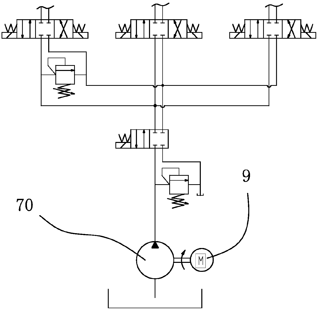
[0053] combine figure 1 and figure 2 As shown, this embodiment provides an engineering vehicle, more specifically, a loader. It includes a vehicle frame 5, on which a traveling device 6 and a power unit assembly 9 are arranged; on the vehicle frame 5, a hydraulic actuator 7 is also provided, and the hydraulic actuator 7 includes a hydraulic oil circuit, a hydraulic cylinder and Load the bucket assembly.

[0054] In this embodiment, the power device assembly 9 includes a gas power device: first, the gas power device is connected to the traveling device 6 through a clutch and a transmission; The hydraulic motor 70 transmission connection on the hydraulic oil circuit of the device; meanwhile, the vehicle frame 5 is also provided with a storage tank (not shown in the figure, preferably a steel cylinder, a Dewar tank, a high-pressure gas tank or gas storage bottle, which is arranged on the vehicle frame); the storage tank is connected to the gas power device through the valve b...

Embodiment 2

[0075] Example 2: See Figure 8 to Figure 11 , the engineering vehicle of this embodiment is basically the same as Embodiment 1, and its main difference is:

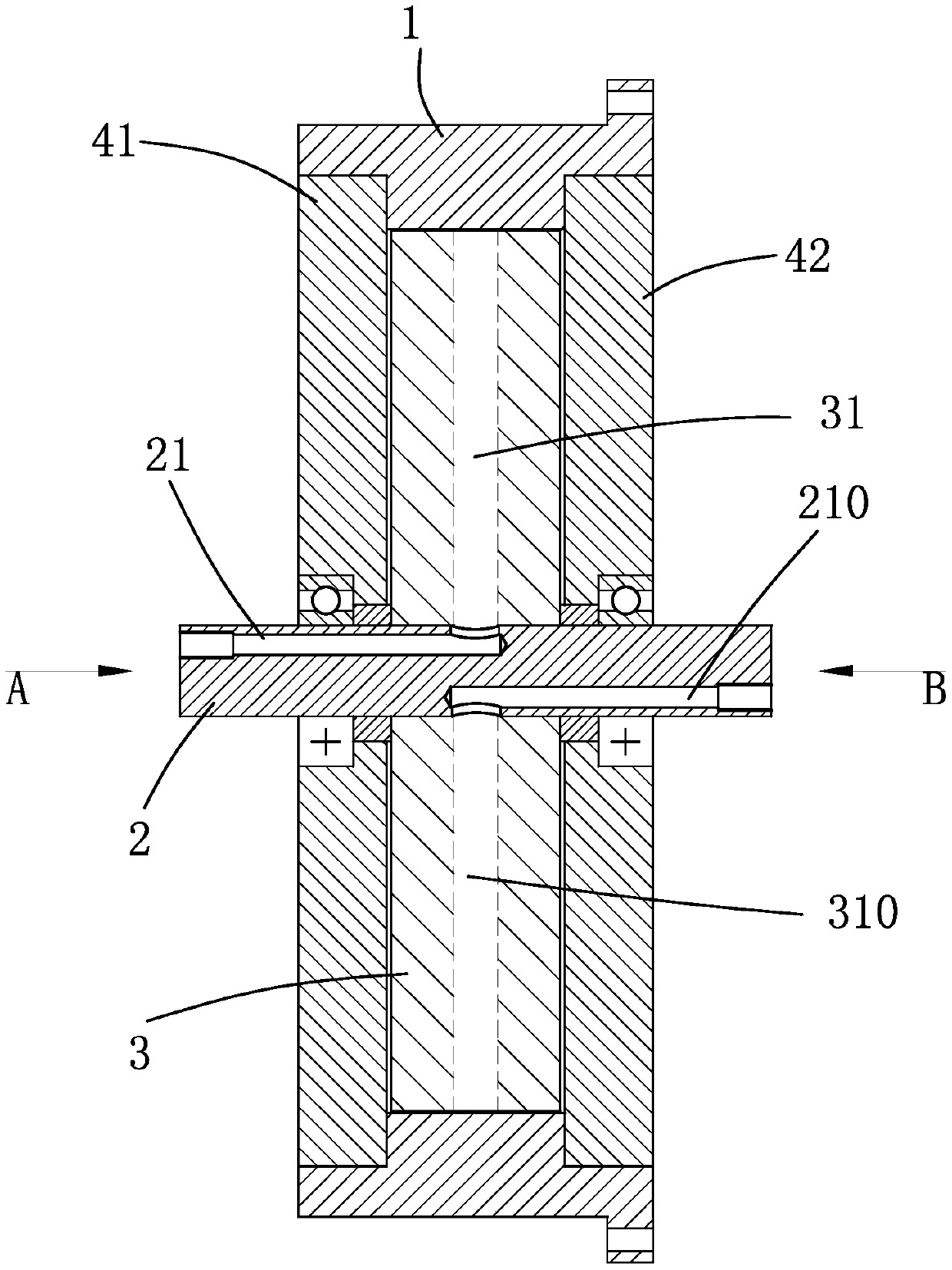
[0076] The gas power device includes 2 independent work units to form a secondary drive structure, that is, the core body 3 is provided with 2 air channels along the circumference, and each air channel includes an air intake channel 31 with a level above 1 and a secondary flushing channel 300 along the The core body 3 is arranged in the circumferential direction and the exhaust flow channel. The gas power device comprises an outer ring 1, a plurality of driving recesses 11 are arranged on the inner ring surface of the inner ring; 2 groups of nozzles, discharge ports, and at least one flushing channel between each group of nozzles and discharge ports; 2 air intake passages 31, 32 are provided on the core body, which correspond to the connecting nozzles; and 2 exhaust passages 310, 320 , which corresponds to the connecte...

Embodiment 3

[0078] Embodiment 3: The engineering vehicle of this embodiment is basically the same as Embodiment 1, and its main difference is:

[0079] The gas power device of the present invention includes 4 or more independent working units to form a multi-stage drive structure, and 3 or more air passages are arranged on the core body along the circumference, and each air passage includes an air intake passage of more than one order and The sub-impulse flow channel and the exhaust flow channel are arranged along the circumference of the core body, and the air intake channel and the exhaust channel are arranged on the mating surfaces of the left and right core bodies. The shaft is provided with the number of air inlet shafts and air outlet shafts corresponding to the number of air passages. Compressed gas enters from the shaft inlet shaft, and is ejected through the core body inlet flow channel to act on the driving recess of the outer ring, pushing the outer ring to rotate and do work. ...


PUM


Abstract

The invention discloses an engineering vehicle. A gas power device is connected to a hydraulic pump to provide an energy source for a hydraulic executing device. The engineering vehicle is simple in structure, high in torque, high in rotating speed, high in transfer efficiency and environmental-friendly. An emission is gas at a reduced pressure, so that the engineering vehicle is low in working noise and free of tail gas pollution. A standby state is extremely low in energy consumption. The gas power device used by the engineering vehicle comprises an outer ring and a core body. An at least one-step secondary flushing runner is arranged between a nozzle and an outlet of an outer ring surface of a core body. Gas enters from a gas inlet and is sprayed from the nozzle of the core body and steps of the secondary flushing runner to be acted to at least two driving concave parts on the circumference of an outer ring, thereby driving the driving concave parts to generate a thrust to push theouter ring to act rotatably so as to output power. Finally, gas is discharged by an exhausting channel through the outlet of the core body.

Description

technical field [0001] The invention discloses an engineering vehicle, which belongs to the technical field of vehicles according to the International Patent Classification (IPC). Background technique [0002] Engineering vehicles are vehicles that need to be used during engineering construction operations. They generally have a traveling device and a hydraulic actuator, both of which share an engine to provide driving power and hydraulic power. [0003] However, after the running gear is shut down, in order to drive the hydraulic actuator, the engine must also be in a standby state or a low-speed working state. The working conditions are unreasonable, and a large amount of exhaust gas is easily generated, and the energy utilization rate is low. [0004] At the same time, the harmful gases and particulate pollutants in the engine exhaust, such as CO, hydrocarbons, nitrogen oxides and other harmful gases, will seriously affect human health. Among them, the combination of CO a...

Claims


Application Information

Patent Timeline
Patent Type & Authority Applications(China)
IPC IPC(8): B60K17/28
CPCB60K17/28
Inventor 许水电李延福许涛
Owner TRANF TECH XIAMEN CO LTD
Why Eureka
Try Eureka