Hydraulic source load self-adaptive system and self-adaptive control method thereof

An adaptive system and hydraulic source technology, which is applied to fluid pressure actuation system components, fluid pressure actuation devices, servo motors, etc., can solve the problem that the flow follow characteristic does not meet the work requirements, and achieve real-time control of power consumption and avoid Effects of sudden changes in movement or output force

Pending Publication Date: 2020-02-25
ZHEJIANG UNIV
View PDF0 Cites 3 Cited by
  • Summary
  • Abstract
  • Description
  • Claims
  • Application Information

AI Technical Summary

Problems solved by technology

Therefore, the traffic following characteristics of traditional load sensing systems do not meet their working requirements

Method used


Image

  • Hydraulic source load self-adaptive system and self-adaptive control method thereof
  • Hydraulic source load self-adaptive system and self-adaptive control method thereof
  • Hydraulic source load self-adaptive system and self-adaptive control method thereof

Examples


Embodiment Construction

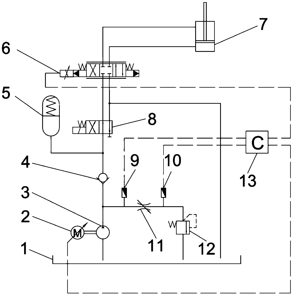
[0032] In order to make the objectives, technical solutions and advantages of the present invention clearer, the technical solutions in the embodiments of the present invention will be described in more detail below in conjunction with the drawings in the embodiments of the present invention. In the drawings, the same or similar reference numerals denote the same or similar elements or elements having the same or similar functions throughout. The described embodiments are some, but not all, embodiments of the invention. The embodiments described below by referring to the figures are exemplary and are intended to explain the present invention and should not be construed as limiting the present invention. Based on the embodiments of the present invention, all other embodiments obtained by persons of ordinary skill in the art without making creative efforts belong to the protection scope of the present invention. Embodiments of the present invention will be described in detail b...


PUM


Abstract

The invention discloses a hydraulic source load self-adaptive system and a self-adaptive control method. The hydraulic source load self-adaptive system comprises a controller, two pressure sensors, adirect-current synchronous motor, a check valve, an energy accumulator, an electro-hydraulic servo valve, an overflow valve, an electrically controlled reversing valve and an adjustable throttle valve. The pressure sensors are arranged at the two ends of the adjustable throttle valve. The input end of the controller is connected with the two pressure sensors. The output end of the controller is connected with the electro-hydraulic servo valve and the direct-current synchronous motor. The inlet end of the adjustable throttle valve is arranged between a gear pump outlet and the check valve. Theoutlet end of the adjustable throttle valve is arranged on the high-pressure side of the overflow valve. The low-pressure side of the overflow valve communicates with an oil tank through an oil way. The energy accumulator is arranged between the electrically controlled reversing valve and the check valve. The input end of the electro-hydraulic servo valve is connected with the electrically controlled reversing valve. The output end of the electro-hydraulic servo valve is connected with a load hydraulic cylinder. According to the hydraulic source load self-adaptive system and the self-adaptivecontrol method, output characteristics of a hydraulic system are matched with the load magnitude through pressure difference signal feedback, and power consumed by a hydraulic source can be controlledeffectively. The hydraulic source load self-adaptive system can be applied to a deep sea hydraulic source, and energy-saving control of the hydraulic source load self-adaptive system is achieved.

Description

technical field [0001] The invention relates to a hydraulic source system, in particular to a hydraulic source load self-adaptive system and an self-adaptive control method thereof, belonging to the technical field of construction machinery hydraulics. Background technique [0002] The power supply mode of underwater submersibles is divided into two types: cables and batteries, and for underwater submersibles operating at large depths, batteries are often used for power supply. As the power source of the underwater submersible, the deep-sea hydraulic source system needs to drive the propulsion system, operating devices, etc. Therefore, improving the efficiency of the hydraulic system and reducing its power consumption is an important part of efficiently utilizing the stored electric energy. [0003] The traditional load sensing system can control the flow output of the system according to the load condition, so as to achieve the effect of high efficiency and self-regulation....

Claims


Application Information

Patent Timeline
Patent Type & Authority Applications(China)
IPC IPC(8): F15B1/04F15B11/028F15B11/08F15B13/04F15B21/02
CPCF15B1/04F15B11/028F15B11/08F15B13/04F15B21/02F15B2201/21F15B2201/31F15B2211/20515F15B2211/253
Inventor 冷建兴田永强刘硕
Owner ZHEJIANG UNIV
Why Eureka
Try Eureka