
Heat treatment method for controlling hardness and deformation of low-carbon alloy steel gear

A technology of low carbon alloy steel and heat treatment method, applied in heat treatment furnace, heat treatment equipment, heat treatment process control and other directions, can solve the problems of high hardness and difficult processing, achieve small heat treatment deformation, reasonable process technology, and solve difficult machining problems Effect

Inactive Publication Date: 2020-02-28
ZHONGNAN TRANSMISSION MACHINERY FACTORY CHANGSHAAVIATION IND
View PDF3 Cites 1 Cited by
  • Summary
  • Abstract
  • Description
  • Claims
  • Application Information

AI Technical Summary

Problems solved by technology

Because the material can be quenched by air cooling, the overall hardness of the part is high during the cooling process after carburizing. After carburizing, the conventional annealing process is used, and the hardness is difficult to meet the requirements of the machining process. The conventional annealing process uses 640~ 660°C for 4-5 hours, that is to say, only one tempering process is carried out after carburizing, and the hardness of the carburized surface will reach above HRC50, which makes it difficult to process when turning to remove the carburized layer before quenching; During the quenching process, distortion will occur due to the influence of structural stress and thermal stress. However, the existing design drawings stipulate that the maximum grinding allowance of the carburized surface after carburizing and quenching is 0.20, and the maximum grinding allowance of the non-working tooth surface is 0.25. The grinding allowance on the surface of the carburizing and quenching layer is uniform, and the heat treatment deformation of the parts must be precisely controlled

Method used


Image

  • Heat treatment method for controlling hardness and deformation of low-carbon alloy steel gear
  • Heat treatment method for controlling hardness and deformation of low-carbon alloy steel gear
  • Heat treatment method for controlling hardness and deformation of low-carbon alloy steel gear

Examples


Embodiment 1

[0035] A spiral bevel gear for an aviation product requires a tooth carburizing depth of 1.20-1.50mm, a tooth carburizing surface hardness of 58-63HRC, and a tooth root cone relative to the root cone simulation size reading of +0.03-+0.15.

[0036] like Figure 7 As shown, a heat treatment method for controlling the hardness and deformation of low-carbon alloy steel gears in this embodiment includes the following steps:

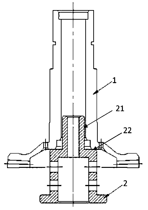
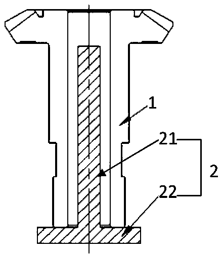
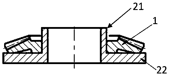
[0037] (1) Low-carbon alloy steel gear part 1 has completed the carburized surface tooth part and runway processing before carburizing, and the remaining surface has a carburized layer turning allowance (greater than 2 times the carburizing depth) so that the low-carbon alloy steel gear Part 1 is overall carburized.

[0038] (2) Low-carbon alloy steel gear part 1 is placed in the sand blowing machine to clean the carburized surface of the runway and the teeth. The corundum sand grain size is 100 mesh and the wind pressure is 0.1MPa to ensure that the sand bl...


PUM


Abstract

The invention discloses a heat treatment method for controlling hardness and deformation of a low-carbon alloy steel gear. The heat treatment method comprises the following steps that a low-carbon alloy steel gear part is pretreated; the pretreated low-carbon alloy steel gear part is subjected to carburizing treatment; the carburized low-carbon alloy steel gear part is firstly placed at the temperature of 650 + / -10 DEG C for first tempering treatment and then placed at the temperature of 630 + / -10 DEG C for second tempering treatment; a carburized layer of the tempered low-carbon alloy steel gear part is removed according to preset requirements, and the tempered low-carbon alloy steel gear part is placed at the temperature of 810 + / -10 DEG C for quenching treatment; and the quenched low-carbon alloy steel gear part is sequentially subjected to cold treatment, tempering treatment and post-treatment. The heat treatment method has the advantages that the hardness of the part after carburizing and before quenching is low, and the thermal deformation of the part after quenching is small.

Description

technical field [0001] The invention relates to the field of heat treatment of low-carbon alloy steel, in particular to a heat treatment method for controlling the hardness and deformation of low-carbon alloy steel gears. Background technique [0002] 18Cr2Ni4WA steel is a low-carbon alloy steel, which is a kind of martensitic steel. After carburizing and quenching, the surface can obtain high hardness, and has excellent strength and toughness. Since the material can be quenched by air cooling, the overall hardness of the part is high during the cooling process after carburizing. After carburizing, the conventional annealing process is used, and the hardness is difficult to meet the requirements of the machining process. The conventional annealing process uses 640~ 660°C for 4-5 hours, that is to say, only one tempering process is carried out after carburizing, and the hardness of the carburized surface will reach above HRC50, which makes it difficult to process when turning...

Claims


Application Information

Patent Timeline
IPC IPC(8): C21D1/18C21D1/673C21D6/04C21D9/32C21D11/00C23C8/22
CPCC21D1/18C21D1/673C21D6/04C21D9/32C21D11/005C23C8/22
Inventor 刘龙凯张志华刘丽婷吴平吴仡璇
Owner ZHONGNAN TRANSMISSION MACHINERY FACTORY CHANGSHAAVIATION IND
Learn More