Compact low-coupling tri-polarized MIMO antenna based on planar structure

A plane-structured, compact technology, applied in the antenna grounding device, the radiating element structure, the antenna grounding switch structure connection, etc., can solve the problems of increasing the low elevation gain, reducing the coupling degree of the antenna radiation unit, and the large size of the antenna. To achieve the effect of improved isolation

Active Publication Date: 2020-02-28
COMMUNICATION UNIVERSITY OF CHINA
View PDF5 Cites 10 Cited by
  • Summary
  • Abstract
  • Description
  • Claims
  • Application Information

AI Technical Summary

Problems solved by technology

Although this antenna achieves triple polarization through a single-layer compact structure, there are still two disadvantages: the antenna size is larger than half a wavelength, and the coupling is larger than -13dB
For example, application 201310121176.8 proposes a microstrip antenna loaded with a parasitic ring, which reduces the zenith signal radiation of the traditional microstrip patch antenna through the parasitic ring, increases the low elevation gain near the horizontal plane, and widens the lobes of the vertical plane Width, the antenna consists of two layers of dielectric boards, using a fixed column to separate the two layers of dielectric boards, resulting in a higher overall profile
Application No. 201620584674.5 Add two parasitic patches with a kitchen knife-shaped slot between two antenna radiating elements. By changing the charge distribution on the dielectric plate, the electric field distribution on the antenna radiating element is changed to reduce the antenna radiating element. The purpose of the coupling degree between, however, the two radiating elements of the structure are separated by a certain distance in the horizontal plane, and the horizontal dimension is larger
[0006] These designs of loading parasitic patches on the antenna increase the section height or plane size of the antenna, which is not conducive to the miniaturization of the antenna or the formation of an array antenna

Method used


Image

  • Compact low-coupling tri-polarized MIMO antenna based on planar structure
  • Compact low-coupling tri-polarized MIMO antenna based on planar structure
  • Compact low-coupling tri-polarized MIMO antenna based on planar structure

Examples


Embodiment 1

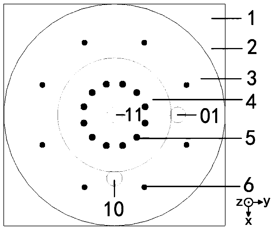
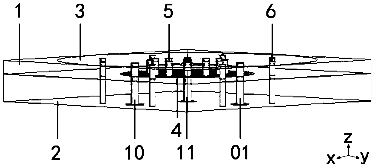
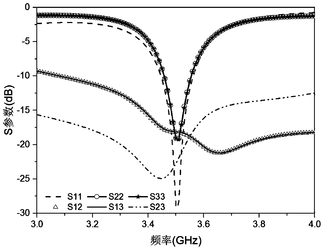
[0029] refer to figure 1 and figure 2 , the antenna consists of a double-layer dielectric plate 1, a grounded metal plate 2, a circular metal patch 3, a circular metal patch 4, twelve connecting circular metal patches 3 and circular metal patches 4, eight second metal vias 6 connecting the circular metal patch 3 and the ground metal plate 2, and three coaxial line feed ports 10, 01, 11.

[0030] Among them, the material of the double-layer dielectric board 1 is the same, both are epoxy resin boards FR4 with a dielectric constant of 4.4, and are stacked on the xoy plane with the origin as the center, and the side length is 42 mm, which is less than the half wavelength corresponding to 3.5 GHz; The metal plate 2 is located on the bottom surface of the lower dielectric plate, and its size is the same as the bottom area of ​​the lower dielectric plate; the circular metal patch 3 is covered on the top surface of the upper dielectric plate as the main radiator; the circular metal ...


PUM


Abstract

The invention discloses a compact low-coupling tri-polarized MIMO antenna based on a planar structure, and belongs to the antenna field of communication technology. The antenna is formed by stacking two layers of dielectric plates. The top surface of the upper dielectric plate is coated with a main radiator metal patch. The bottom surface of the lower dielectric plate is a grounding metal plate; aparasitic metal patch is arranged between the two layers of dielectric plates; a plurality of first metal via holes connected with the parasitic metal patch and the main radiator metal patch are formed in the upper dielectric plate; and a plurality of second metal via holes connected with the main radiator metal patch and the grounding metal plate are formed in the two layers of dielectric plates. Feed is carried out at different positions of the main radiator metal patch of the antenna, and three orthogonal polarizations can be realized at the same frequency. Compared with an existing tri-polarized MIMO antenna, the tri-polarized MIMO antenna has smaller size and lower coupling, is more suitable for small terminal equipment, is more suitable for forming an antenna array, and can also beused as a unit of a compact large-scale MIMO antenna.

Description

technical field [0001] The invention designs a compact low-coupling three-polarization MIMO antenna based on a planar structure, and belongs to the antenna field of communication technology. Background technique [0002] The fifth-generation communication technology that has been commercialized indicates that mobile communication is developing in the direction of faster speed, lower bit error rate, shorter delay, and higher channel capacity. In a wireless communication system, by using multiple antennas at the transmitting end and the receiving end at the same time, that is, using Multiple-Input Multiple-Output (MIMO) technology, the communication system can have stable transmission and increased channel capacity. advantage. [0003] A MIMO antenna has been disclosed in the prior art. By adding a certain number of metal vias connecting the metal patch and the grounded metal plate, three orthogonally polarized antennas can be generated by the same radiator. Although this an...

Claims


Application Information

Patent Timeline
Patent Type & Authority Applications(China)
IPC IPC(8): H01Q1/38H01Q1/48H01Q1/50
CPCH01Q1/38H01Q1/48H01Q1/50
Inventor 朴大志左杰张林坤王亚金
Owner COMMUNICATION UNIVERSITY OF CHINA
Why Eureka
Try Eureka