Heat preservation tee pipeline

A pipeline and three-way technology, applied in the field of thermal insulation three-way pipeline, can solve the problems of affecting the thermal insulation effect, time-consuming and laborious, heat dissipation, etc., and achieve the effects of good mechanical performance, damage prevention, and thermal insulation.

Inactive Publication Date: 2020-03-06
宋晓明
View PDF10 Cites 0 Cited by
  • Summary
  • Abstract
  • Description
  • Claims
  • Application Information

AI Technical Summary

Problems solved by technology

In the above technical solutions, thermal insulation components are assembled and wrapped on the outside of the three-way pipe to realize the thermal insulation effect on the three-way pipe, but it is inconvenient to work, time-consuming and labor-intensive, and the joint of the thermal insulation component assembled on the outside of the three-way pipe has problems. Gaps can easily cause heat loss and affect the insulation effect

Method used


Image

  • Heat preservation tee pipeline
  • Heat preservation tee pipeline
  • Heat preservation tee pipeline

Examples


Embodiment 1

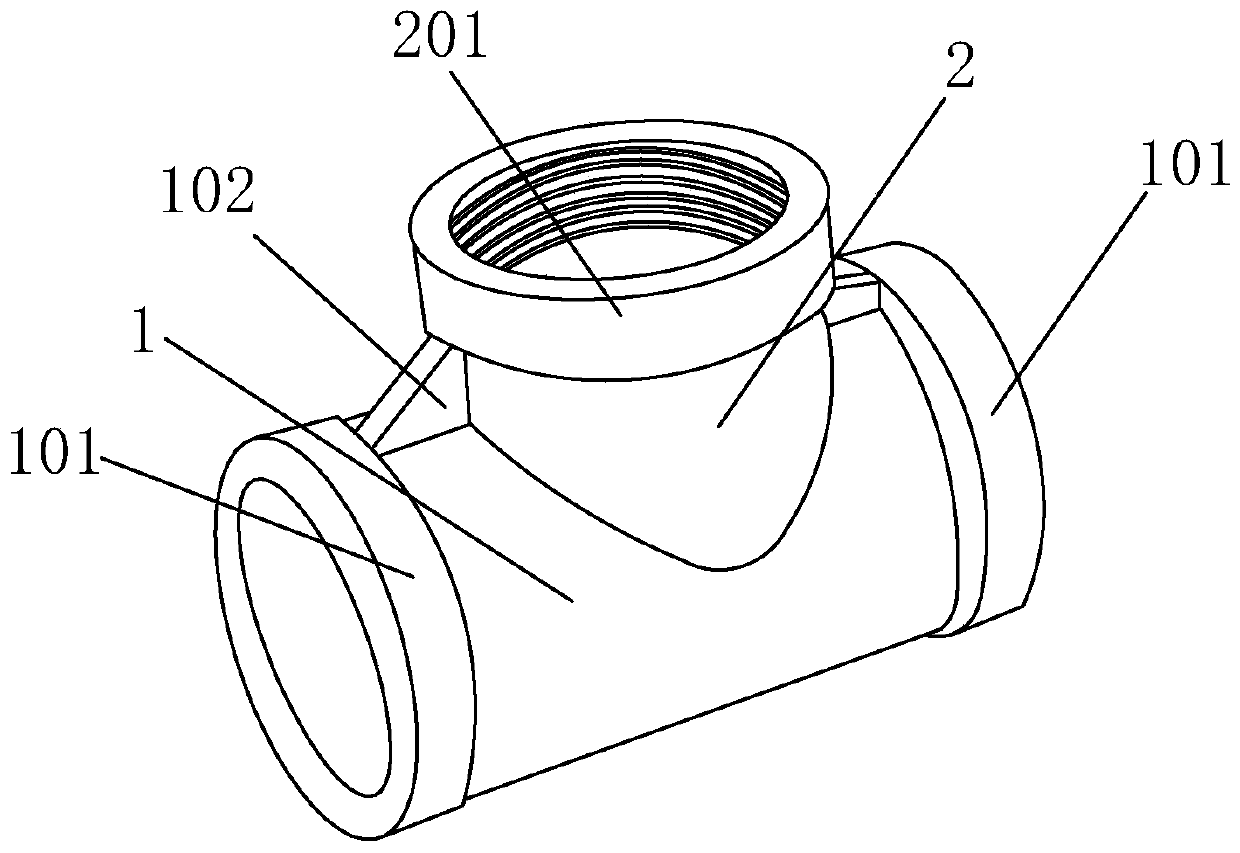
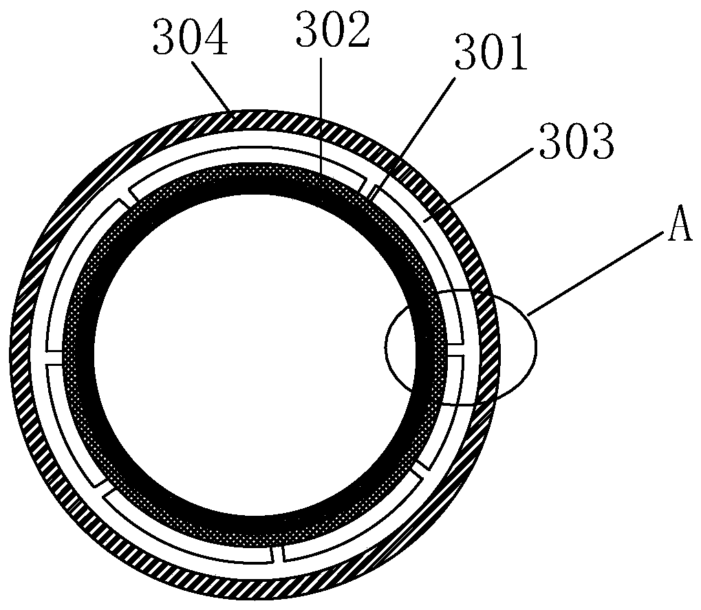
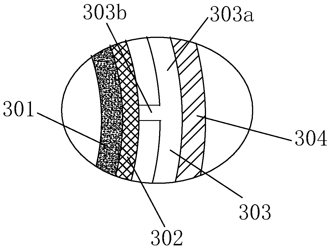
[0026] Such as figure 1 It is a schematic structural view of a three-way pipeline of the present invention, comprising a main pipeline 1 and a branch pipeline 2 integrally connected to the side wall of the main pipeline, the main pipeline is perpendicular to the branch pipeline, and the main pipeline and the branch pipeline communicate with each other. Between the side wall of the pipeline and the side wall of the branch pipeline, a fixing block 102 is provided to reinforce the connection between the main pipeline and the branch pipeline, and a main connecting part 101 is respectively provided at both ends of the main pipeline, and the free ends of the branch pipeline A sub-connection part 201 is provided at the end, and the main connection part and the sub-connection part are both cylindrical and the inner wall is provided with threads, such as figure 2 , image 3 are the cross-sectional schematic diagrams of branch pipes or branch pipes and figure 2 The schematic diagram...

Embodiment 2

[0034] Such as figure 1 It is a schematic structural view of a three-way pipeline of the present invention, comprising a main pipeline 1 and a branch pipeline 2 integrally connected to the side wall of the main pipeline, the main pipeline is perpendicular to the branch pipeline, and the main pipeline and the branch pipeline communicate with each other. Between the side wall of the pipeline and the side wall of the branch pipeline, a fixing block 102 is provided to reinforce the connection between the main pipeline and the branch pipeline, and a main connecting part 101 is respectively provided at both ends of the main pipeline, and the free ends of the branch pipeline A sub-connection part 201 is provided at the end, and the main connection part and the sub-connection part are both cylindrical and the inner wall is provided with threads, such as figure 2 , image 3 are the cross-sectional schematic diagrams of branch pipes or branch pipes and figure 2 The schematic diagram...


PUM

PropertyMeasurementUnit
Thermal stabilization timeaaaaaaaaaa
Tensile strengthaaaaaaaaaa
Vicat softening temperatureaaaaaaaaaa

Abstract

The invention relates to the technical field of pipelines, and discloses a heat preservation tee pipeline. The heat preservation tee pipeline includes a main pipeline and branch pipelines integrally connected to the side wall of the main pipeline, the main pipeline and the branch pipelines are in communication, the two ends of the main pipeline are each provided with a main connecting portion, thefree ends of the branch pipelines are each provided with a sub-connecting part, and the main pipe and the branch pipelines each comprise a cylindrical conveying layer, a heat preservation layer, a heat insulating layer and a metal layer in sequence from inside to outside. By means of the heat preservation tee pipeline, an externally-assembled heat insulation sleeve is not needed, time and labor are saved, and the good heat preservation effect is achieved; and the conveying layers are made of heat-resistant polyvinyl chloride, the excellent mechanical properties and compactness are achieved, and it can be ensured that leakage or penetration of transported materials is avoided.

Description

technical field [0001] The invention relates to the technical field of pipelines, in particular to a thermal insulation three-way pipeline. Background technique [0002] In the process of pipeline insulation, people mostly use straight-shaped heat-insulating pipe fittings. However, when encountering joints or tees of pipes, the straight-shaped heat-insulating pipe fittings can only be cut and assembled, or fiber insulation such as glass wool can be used. The material is wound on the tee pipe without heat preservation performance, or it is completed by assembling the heat preservation pipes of different specifications, so that the tee pipe has the effect of heat preservation and avoids the heat loss inside the pipe. However, this brings a lot of inconvenience to the work, is time-consuming and laborious, and it is inevitable to leave more gaps during the assembly process, which affects the thermal insulation effect of the tee pipe. For example, Chinese Patent Publication No....

Claims


Application Information

Patent Timeline
IPC IPC(8): F16L41/02F16L59/02F16L59/07F16L59/10B32B15/04B32B17/06B32B17/10B32B27/12B32B27/32B32B33/00C08L27/06C08L91/06C08K9/04C08K3/26
CPCB32B15/04B32B17/06B32B17/10B32B27/12B32B27/32B32B33/00C08K2003/265C08L27/06C08L2203/18F16L41/021F16L59/02F16L59/07F16L59/103C08L91/06C08K9/04C08K3/26
Inventor 宋晓明
Owner 宋晓明
Why Eureka
Try Eureka