Primary evaporation preparation method of plated metal film for battery
A metal plating and battery technology, applied in battery pack parts, metal material coating process, circuit and other directions, can solve the problems that affect the performance of the aluminized film, the bonding force of the aluminized structural layer is not strong enough, and the delamination is prone to occur. Achieve the effect of improving the bonding effect, ensuring uniform cooling effect, and simple overall structure
- Summary
- Abstract
- Description
- Claims
- Application Information
AI Technical Summary
Problems solved by technology
Method used
Image

Examples
Embodiment 1
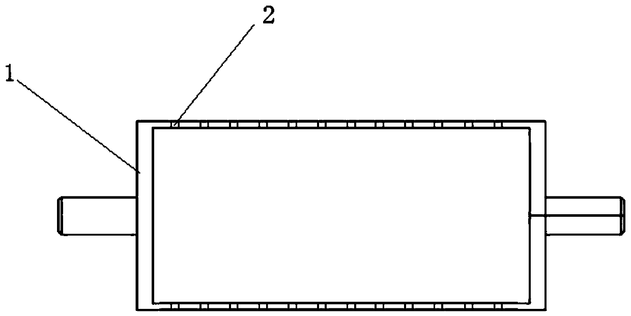
[0031] A method for preparing a metallized film for a battery by primary vapor deposition. The base film is attached to a cooling roller 1 and sent into a vacuum vapor deposition chamber. The vacuum vapor deposition chamber is provided with an evaporation mechanism with metal materials (evaporation boats, etc. can be used) , when the vacuum degree in the vacuum evaporation chamber reaches the set threshold requirement, the metal material is heated and melted and evaporated in the evaporation mechanism to form metal vapor, so that the base film is immersed in the metal vapor, that is, the primary evaporation of the metal layer is completed.
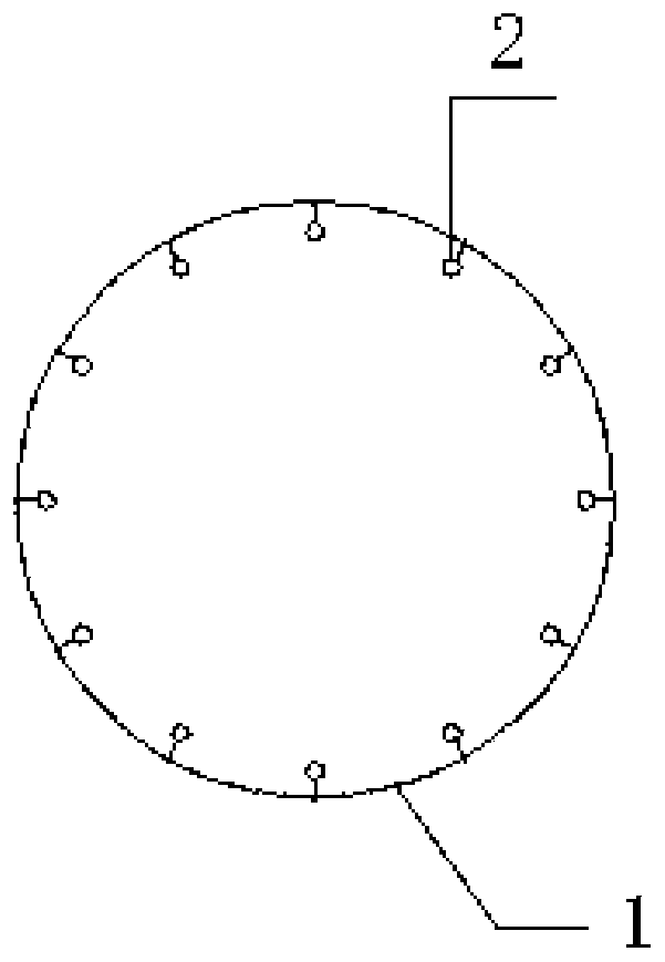
[0032] Its structure see figure 1 As shown, the cooling roll 1 includes a roller body with a built-in circulating cooling channel, and micropores 2 are distributed on the surface of the roller body. A gas chamber connected to the micropores 2 is arranged inside the roller body, and the gas chamber is connected to the external gas through th...
Embodiment 2
[0049] Compared with Example 1, most of them are the same, except that in this example, the relative humidity is controlled to be 60%.
Embodiment 3
[0051] Compared with Example 1, most of them are the same, except that in this example, the base film is also subjected to surface treatment before being sent into the vacuum evaporation chamber, and the surface treatment method is preferably corona treatment.
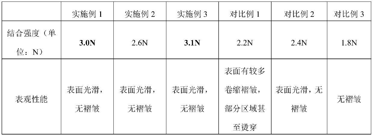
[0052] At the same time, the bonding strength test was carried out on the aluminum-coated films obtained in the above-mentioned Examples 1-Example 2 and Comparative Example 1-Comparative Example 3 (one-time vapor deposition to the same thickness, which is about 800nm), and the obtained performance results are shown in Table 1 below. .
[0053] Table 1 The performance of each aluminum-coated film product
[0054]
[0055] Note: Downstream manufacturers require that the bonding strength of the metal layer of the aluminized film product be ≥ 2N. Generally, 2N is regarded as a qualified product for delivery, and a product greater than or equal to 3N is regarded as an excellent product.
[0056] From the measured data i...
PUM
| Property | Measurement | Unit |
|---|---|---|
| Thickness | aaaaa | aaaaa |
Abstract
Description
Claims
Application Information