DC transformer

A DC transformer, positive electrode technology, applied in the direction of converting DC power input to DC power output, instruments, adjusting electrical variables, etc., can solve the problems of high cost and large size of DC transformer, and achieve low production cost, size and capacity reduction. , to avoid the effect of partial discharge phenomenon

Inactive Publication Date: 2020-03-06
XIAN XJ POWER ELECTRONICS TECH +5
View PDF3 Cites 0 Cited by
  • Summary
  • Abstract
  • Description
  • Claims
  • Application Information

AI Technical Summary

Problems solved by technology

[0004] The purpose of the present invention is to provide a DC transformer, which is used to solve the problems of large volume and high cost of DC transformers in the prior art

Method used


Image

  • DC transformer
  • DC transformer
  • DC transformer

Examples


Embodiment 1

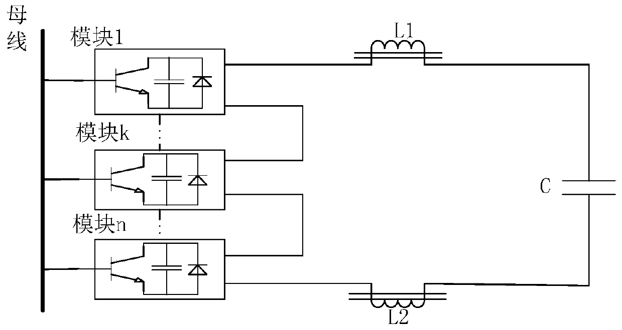
[0025] Such as figure 2 The shown DC transformer includes at least n DC / DC modules, which are respectively module 1, ..., module k, ..., module n, and the output terminals of each DC / DC module are connected to distributed inductance circuits with the same structure, Taking the distributed inductance circuit of module 1 as an example, the distributed inductance circuit includes: a positive inductance L1 with an iron core, a negative inductance L2 with an iron core, and a capacitor module (namely capacitor C1).

[0026] Among them, the positive inductor L1 with an iron core is used to connect the positive pole of the output terminal line of the module 1, and the negative pole inductor L2 with an iron core is used to connect the negative pole of the output terminal line of the module 1; and, the positive pole inductor L1 with an iron core and the negative pole inductor A capacitor module (capacitor C1) is arranged in series between L2.

[0027] The distributed inductance circui...

Embodiment 2

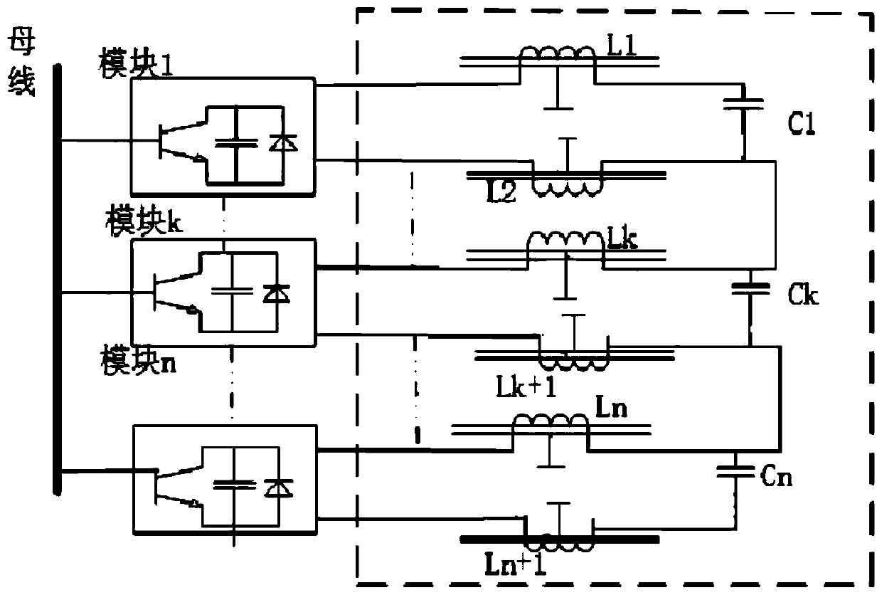
[0032] In the medium-voltage and high-voltage DC distribution network, when the DC transformer in the above-mentioned embodiment 1 adopts a modular cascade topology, due to the lack of electrical connection between the iron core in the DC transformer and the main circuit, a floating potential will be generated. When the electric field When the intensity is uneven, the floating potential will generate a certain electric field, which will cause discharge phenomenon, and in severe cases, the insulating layer will be burned, affecting the stable operation of the equipment. Therefore, on the basis of the DC transformer in Embodiment 1, this embodiment proposes a DC transformer, such as image 3 As shown, in each distributed inductance circuit, the iron core of the negative inductor is grounded, and the iron core of the positive inductor is grounded, which effectively reduces the floating potential of the DC transformer inductor core, avoids the partial discharge phenomenon of the DC...

Embodiment 3

[0034] In order to solve the problems of large volume, high cost and floating potential of the DC transformer at the same time, this embodiment proposes a DC transformer, such as Figure 4 As shown, it includes at least n DC / DC modules, which are respectively module 1, ..., module k, ..., module n, and the output terminals of each DC / DC module are connected with a distributed inductance circuit with the same structure, and module 1 Taking the distributed inductance circuit as an example, the distributed inductance circuit includes:

[0035] Positive inductance L1 with iron core, negative inductance L2 with iron core, and a capacitor module, the capacitor module includes positive capacitor C1 and negative capacitor C2, positive capacitor C1 and negative capacitor C2 are connected in series, positive capacitor C1 and negative capacitor C2 The series point (that is, the neutral point of the capacitor) is connected to the iron core of the positive inductor L1 through the first res...


PUM


Abstract

The invention relates to a DC transformer and belongs to the technical field of DC distribution networks. The DC transformer includes at least two DC / DC modules, wherein the output end of each DC / DC module is connected to a distributed inductance circuit. Each distributed inductance circuit includes a positive inductor with an iron core to be connected to the positive electrode of the output lineof the DC / DC module; a negative inductor with an iron core to be connected to the negative electrode of the output line of the DC / DC module; and a capacitor module connected in series between the positive inductor with the iron core and the negative inductor with the iron core. The distributed inductance circuits of the respective DC / DC module are connected in series to form the output end of theDC transformer. The positive inductors, the negative inductors, and the capacitor modules in the DC transformer of the present invention are all small in size, that is, the sizes and capacities of theinductors and capacitors are correspondingly reduced so as to achieve high degree of integration and correspondingly reduce the size of the DC transformer. In addition, the small-sized inductors andcapacitors do not highly require a production process and thus have low production cost so as to reduce the production cost of the DC transformer.

Description

technical field [0001] The invention relates to a DC transformer and belongs to the technical field of DC distribution network. Background technique [0002] With the increase of DC distribution network projects and the rapid development of DC distribution network technology, DC equipment (such as DC transformers) have been more widely used in actual DC transmission projects. Larger features, the increase in the number of DC power distribution equipment modules required and the increase in equipment volume, how to better access distributed power sources and DC loads has become a more serious problem, so it is urgently needed to be smaller in size and more integrated High DC equipment to improve system security and operating efficiency. [0003] In the prior art, the DC transformer adopts DC / DC modules connected in series to connect inductances L1 and L2 with iron cores in a unified way, and output them to the capacitor C. Such as figure 1 As shown, the busbar is connected...

Claims


Application Information

Patent Timeline
Patent Type & Authority Applications(China)
IPC IPC(8): H02M3/00
CPCH02M3/00H02M1/0067
Inventor 刘增哲安昱柳龙杨欣然张帆石松盛万兴李蕊吴鸣孙丽敬李彬彬聂明珍
Owner XIAN XJ POWER ELECTRONICS TECH
Why Eureka
Try Eureka