Ultra-wideband microwave sampling circuit and sampling method based on nonlinear transmission line

A technology of nonlinear transmission line and sampling circuit, which is applied in the field of ultra-wideband microwave sampling circuit and sampling, which can solve the problem that it is difficult to realize the requirements of large bandwidth and high frequency band, the requirements of wider frequency band testing, and the requirements of instruments, etc. problems, to achieve the effect of expanding working bandwidth, low cost, and easy debugging

Pending Publication Date: 2020-03-06
THE 41ST INST OF CHINA ELECTRONICS TECH GRP
View PDF12 Cites 2 Cited by
  • Summary
  • Abstract
  • Description
  • Claims
  • Application Information

AI Technical Summary

Problems solved by technology

The disadvantage of the prior art is that it is limited by the transition time of the step recovery diode and the lifetime of the carrier. The narrow pulse width generated by the step recovery diode is limited, and only a narrow pulse with a rising edge of tens of picoseconds can be generated. The sampling circuit The working frequency can only reach about 20GHz, which cannot meet the requirements of wider frequency band testing
Narrow bandwidth, very limited, it is difficult to meet the requirements for the use of large bandwidth and high frequency band
[0004] With the rapid development of electronic technology, various measurement and testing equipment are constantly developing towards high frequency and broadband, which puts forward higher requirements for the working bandwidth of sampling technology. The previous sampling technology can no longer meet the needs of the instrument.

Method used


Image

  • Ultra-wideband microwave sampling circuit and sampling method based on nonlinear transmission line
  • Ultra-wideband microwave sampling circuit and sampling method based on nonlinear transmission line
  • Ultra-wideband microwave sampling circuit and sampling method based on nonlinear transmission line

Examples


Embodiment Construction

[0021] The following will clearly and completely describe the technical solutions in the embodiments of the present invention with reference to the drawings in the embodiments of the present invention.

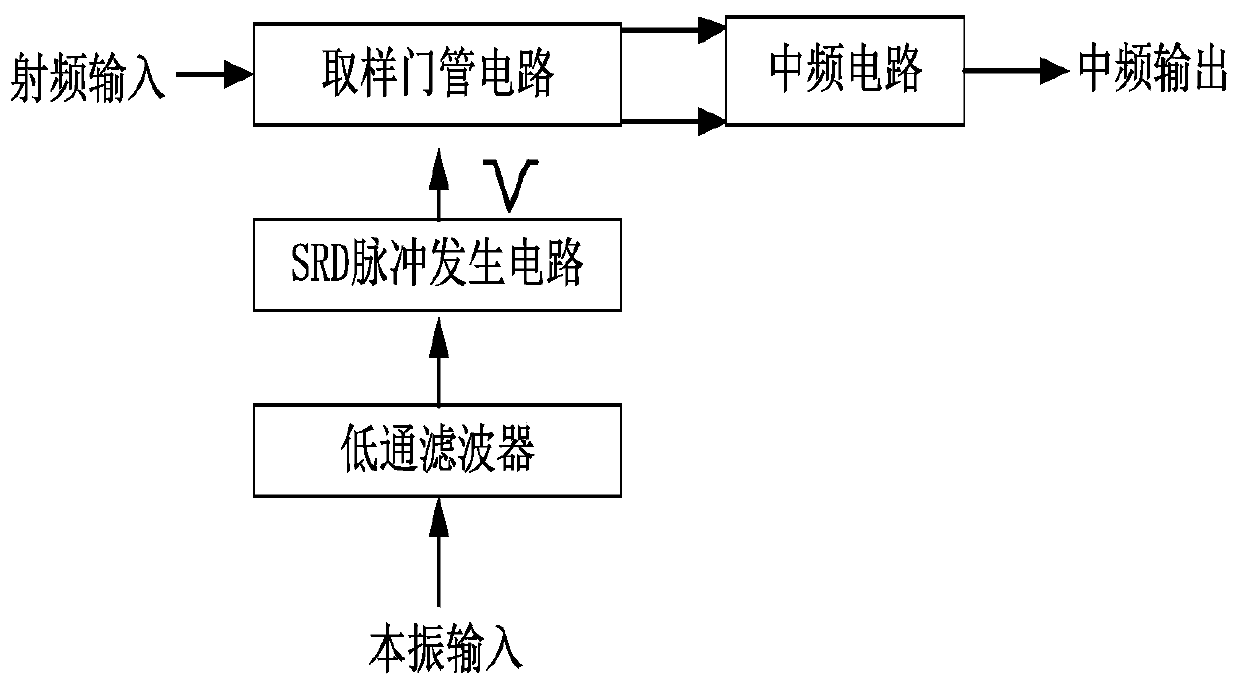
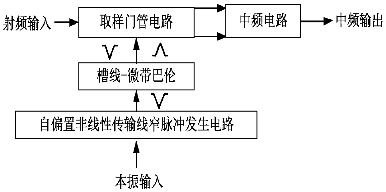
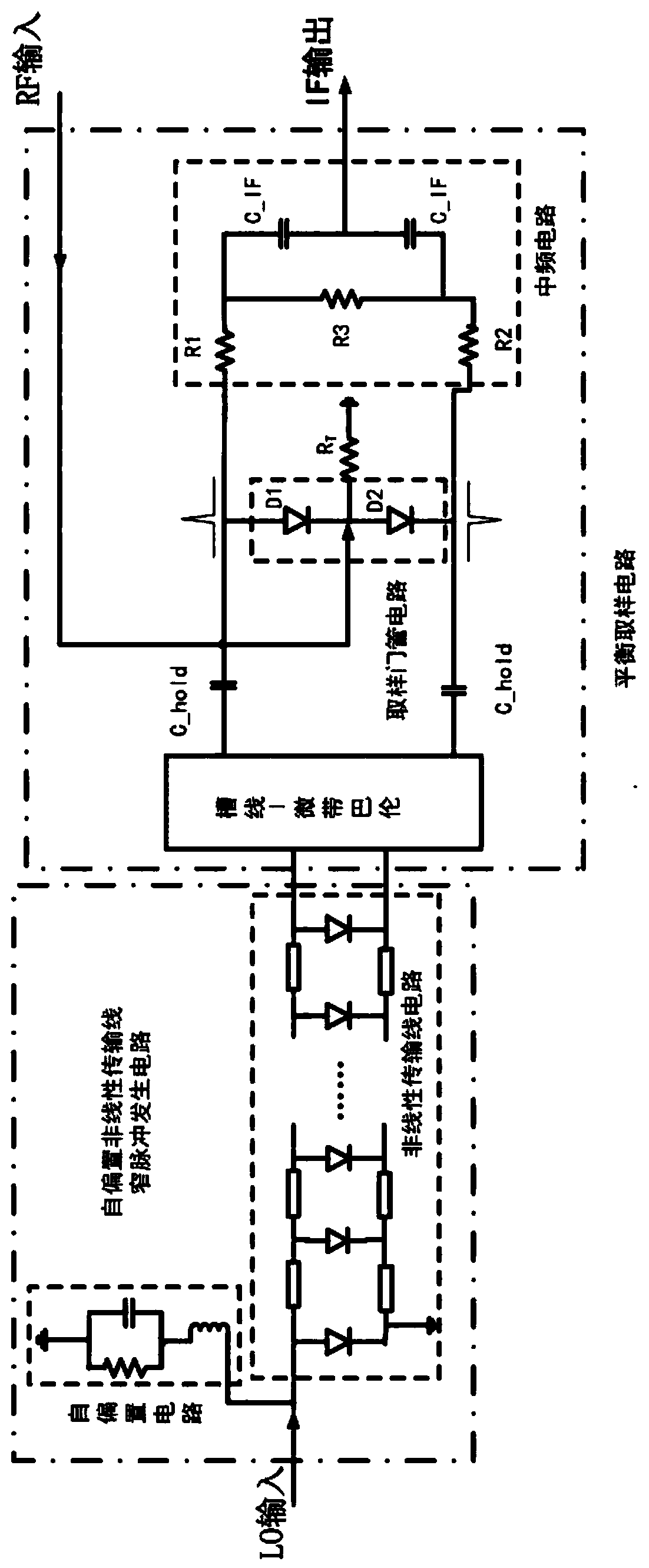
[0022] The invention provides an ultra-wideband microwave sampling circuit based on a nonlinear transmission line, such as figure 2 and image 3 As shown, it includes sequentially connected self-biased nonlinear transmission line narrow pulse generator circuit, slot line-microstrip balun, sampling gate circuit and intermediate frequency circuit. The intermediate frequency circuit in this embodiment is a self-biased intermediate frequency circuit.

[0023] The self-biased nonlinear transmission line narrow pulse generating circuit is implemented by a monolithic microwave integrated circuit chip (MMIC). The self-biased nonlinear transmission line narrow pulse generating circuit includes a self-biased circuit and a nonlinear transmission line circuit. The nonlinear transmission...


PUM


Abstract

The invention discloses an ultra-wideband microwave sampling circuit based on a nonlinear transmission line and a sampling method. The sampling circuit comprises a self-biased nonlinear transmission line narrow pulse generation circuit, a slot line-microstrip balun, a sampling gate tube circuit and an intermediate frequency circuit which are connected in sequence, a local oscillator signal entersthe self-biased nonlinear transmission line narrow pulse generation circuit; a series of narrow pulse local oscillation signals are generated; according to the sampling circuit and the sampling methoddisclosed by the invention, a radio frequency signal is converted into a pair of sampling pulses with equal amplitude and opposite phases through the slot line-microstrip balun, the radio frequency signal is sampled on the sampling gate tube circuit and is output after being shaped by the intermediate frequency circuit, so that the sampling of the radio frequency signal is completed, and the sampling circuit and the sampling method disclosed by the invention can realize ultra-wideband frequency coverage from radio frequency to millimeter wave frequency; the self-bias circuit is simple in design, easy to implement and adjust, high in expansibility and low in cost.

Description

technical field [0001] The invention relates to microwave sampling technology, in particular to an ultra-broadband microwave sampling circuit and sampling method based on nonlinear transmission lines. Background technique [0002] Microwave signal sampling technology has been widely used in sampling oscilloscopes, vector network analyzers, spectrum analyzers, ultra-wideband receivers and other measuring and testing instruments. Sampling technology adopts the principle of sample-and-hold, and its main function is to complete the frequency conversion and convert the microwave signal into a lower-frequency intermediate frequency signal, while keeping the amplitude information and phase information of the microwave signal from being lost. Sampling is the core factor that affects the main indicators such as the upper limit operating frequency of the test instrument and the dynamic range of the whole machine. [0003] In the sampling technology, it is necessary to use a narrow pu...

Claims


Application Information

Patent Timeline
Patent Type & Authority Applications(China)
IPC IPC(8): H03K3/017H03K5/24H03K7/08
CPCH03K3/017H03K5/2463H03K7/08
Inventor 张士斌徐从玉范国清代秀解本琦朱伟峰
Owner THE 41ST INST OF CHINA ELECTRONICS TECH GRP
Why Eureka
Try Eureka