Automatic vacuum spraying system

A vacuum spraying and nozzle technology, applied in chemical instruments and methods, chemical/physical processes, dissolution, etc., can solve problems such as failure to meet food hygiene requirements, single auger unable to fully stir materials, and unclean inside of the tank. , to achieve the effect of fast cleaning, good sealing performance and easy cleaning

Pending Publication Date: 2020-03-20
远腾自动化设备(扬州)有限公司
View PDF8 Cites 2 Cited by
  • Summary
  • Abstract
  • Description
  • Claims
  • Application Information

AI Technical Summary

Problems solved by technology

But its shortcomings are: the inner wall of the spiral casing and the internal spiral blades are cleaning dead angles, which cannot be cleaned by compressed air or manually, and the added grease is atomized and sprayed, and will be bonded to the spiral with the powder in the material; the sprayed material After many times, the inside of the tank is not cleaned cleanly, which is easy to breed bacteria, which makes it impossible to meet the requirements of food hygiene; the conical discharge door is easy to stick to the material, resulting in lax closure, and there is a risk of air leakage; the single auger cannot fully stir the material, spraying Insufficient uniformity, the internal volume of the tank is not large enough, and the efficiency of spraying and processing materials is low

Method used


Image

  • Automatic vacuum spraying system
  • Automatic vacuum spraying system
  • Automatic vacuum spraying system

Examples


Embodiment 1

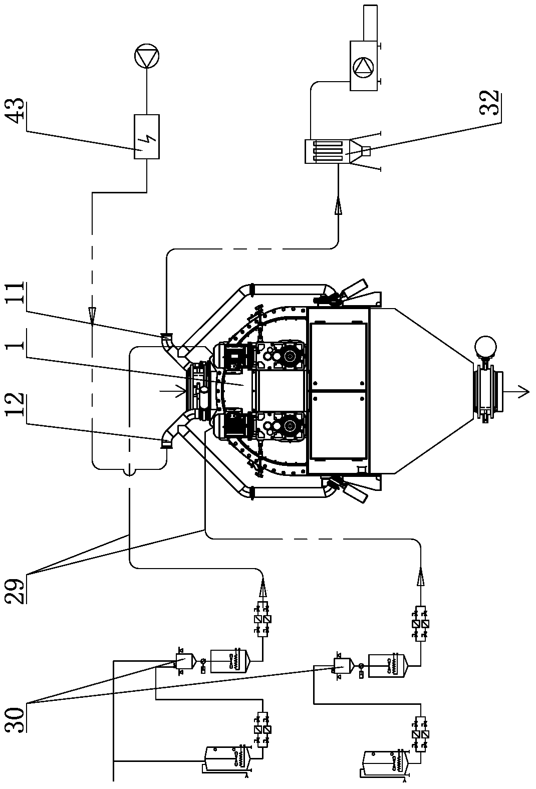
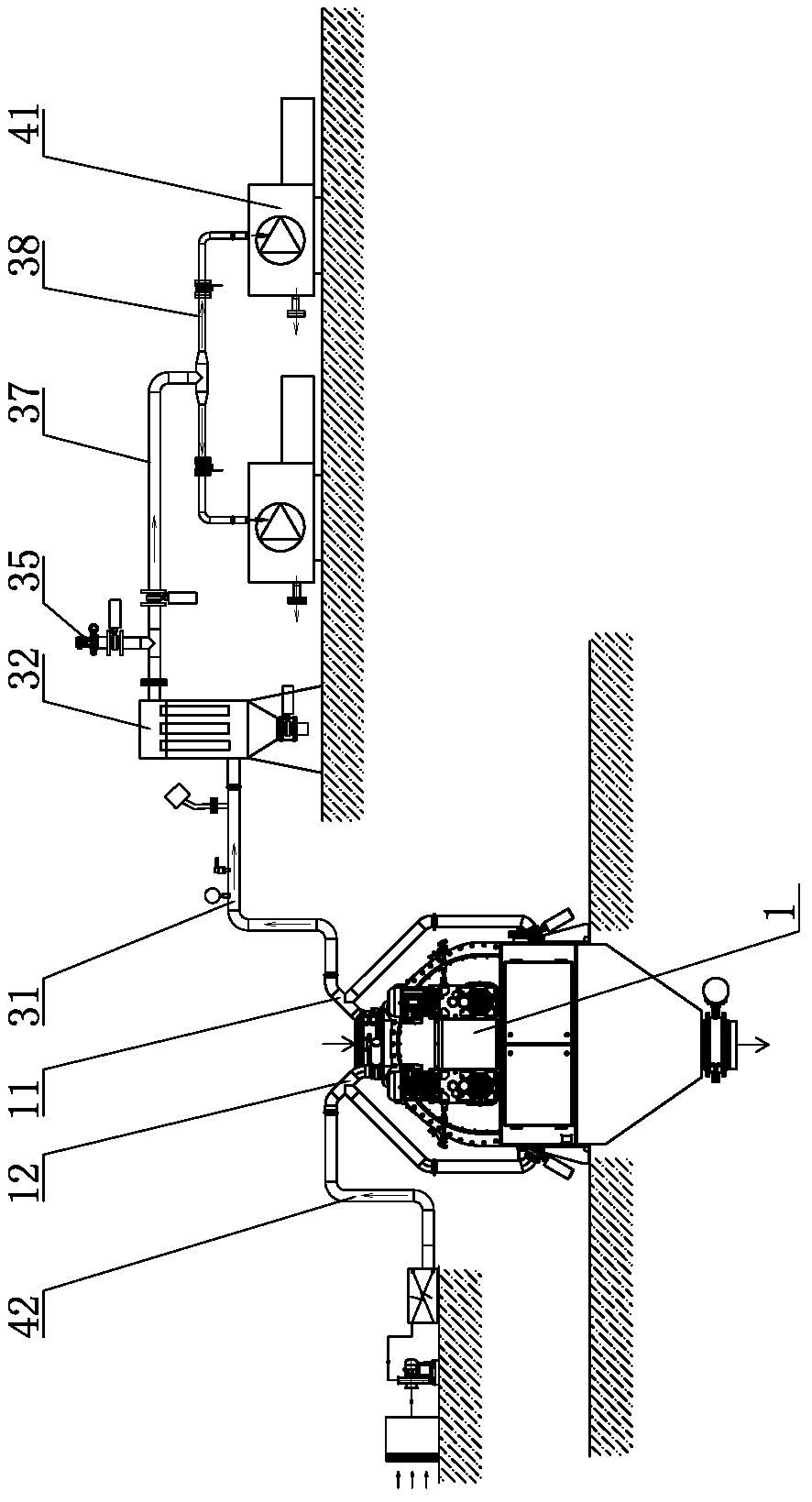
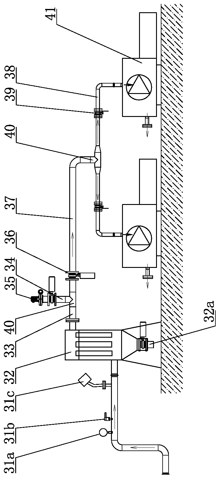
[0034] Such as Figure 1-13 As shown, it is an automatic vacuum spraying system, which includes a spraying host 1, a feeding port 2 is arranged on the top of the spraying host 1, a mixing chamber 101 is arranged inside the spraying host 1, a discharge port 9 is arranged at the bottom of the spraying host 1, and a feeding port 9 is arranged on the bottom of the spraying host 1. Disc valves 36 are provided at the port 2 and the discharge port 9; the mixing chamber 101 includes two left-right symmetrical sub-chambers 101a, and a stirring shaft 3 is rotatably arranged in the two sub-chambers 101a, and the stirring shaft 3 Set in parallel with the length direction of the sub-chamber 101a of the spraying host 1, a number of paddles 5 are staggeredly arranged on the stirring shaft 3, and each paddle 5 on the two stirring shafts 3 is staggered and arranged along the circumferential direction, and the two stirring shafts 3 and The rotary drive mechanism is connected by transmission, an...

Embodiment 2

[0045] Such as Figure 14 and 15 , the difference from Embodiment 1 is that the first nozzle assembly 13 is connected to the pumping pipeline 1301 located above, and the first nozzle assembly 13 includes a left branch pipe one 1301a, a right branch pipe one 1301b and a right branch pipe two 1301c, six nozzles 26 are arranged on the left branch pipe 1301a, and four nozzles 26 are arranged on the right branch pipe one 1301b and the right branch pipe two 1301c; the second nozzle assembly 13 is connected with the pumping pipeline 1302 located below connection, the second nozzle assembly 13 includes a left branch pipe two 1302a and a right branch pipe three 1302b, four nozzles 26 are arranged on the left branch pipe two 1302a, two nozzles 26 are arranged on the right branch pipe three 1302b, and the left branch pipe two 1302a is set corresponding to the left branch pipe 1301a, and the right branch pipe 3 1302b is set corresponding to the right branch pipe 1 1301b and the right bra...


PUM


Abstract

The invention discloses an automatic vacuum spraying system used in the fields of food, pet food and aquatic feed processing. The automatic vacuum spraying system comprises a spraying host, wherein afeeding port is formed in the top of the spraying host; a mixing cavity is formed in the spraying host; a discharge hole is formed in the bottom of the spraying host; the mixing cavity comprises two sub-cavities which are symmetrical in a left-right direction; stirring shafts are respectively arranged in the two sub-cavities; a plurality of paddles are arranged on each stirring shaft in a staggered manner; the stirring shafts are in transmission connection with a rotary driving mechanism; a discharging port is formed in the bottom of each sub-cavity, and a discharging door is correspondingly arranged at each discharging port; a vacuumizing pipe and a hot air drying pipe are arranged on the upper side of the spraying host; a nozzle assembly is arranged at the top of the spraying host; liquid adding equipment is connected to the head end of a pumping pipeline of the nozzle assembly; and material adding equipment is correspondingly arranged above the feeding hole. According to the invention, the mixing cavity of the spraying host is convenient to clean, requirements of food hygiene can be met, and spraying efficiency is higher.

Description

technical field [0001] The invention belongs to the field of food, pet food and aquatic feed processing, and in particular relates to a vacuum spraying system. Background technique [0002] In the prior art, there is a vacuum spraying machine, its patent application number: 201410516694.4; application date: 2014-09-30; its structure includes a tank body and an auger arranged inside the tank body, the auger and the top shaft of the tank body Connected, there is a circular outlet at the bottom of the tank, and a valve is installed at the outlet. The top of the valve is a conical body, the tip of the cone points to the auger, the conical body is coaxial with the auger, and the conical body The conical surface of the auger is sealed with the circular discharge port, and the spiral blade of the auger extends to the bottom of the tank along the conical surface, and a telescopic device is installed at the bottom of the valve to drive the discharge valve to move up and down. The he...

Claims


Application Information

Patent Timeline
IPC IPC(8): B01F7/18B01F13/10B01F15/02
CPCB01F27/90B01F33/811B01F35/7179
Inventor 李洋王新文龚勋
Owner 远腾自动化设备(扬州)有限公司
Why Eureka
Try Eureka