
Plasma chemical vapor deposition system and method

A chemical vapor deposition and plasma technology, which is applied in the field of plasma chemical vapor deposition system, can solve the problems of gas waste, unstable deposition atmosphere, and difficulty in avoiding external impurity pollution, etc., to reduce gas cost, overcome large gas consumption, The effect of ensuring stability

Active Publication Date: 2022-02-11
CHINA BUILDING MATERIALS ACAD
View PDF5 Cites 0 Cited by
  • Summary
  • Abstract
  • Description
  • Claims
  • Application Information

AI Technical Summary

Problems solved by technology

The gas after the process reaction is also directly discharged from the deposition system, resulting in a large amount of gas waste
In addition, due to its semi-open structure, the deposition site is directly connected to the atmosphere, so it is difficult to avoid contamination by external impurities, and the fluctuation of external air pressure directly leads to insufficient stability of the deposition atmosphere, which affects the stability of the prepared material

Method used


Image

  • Plasma chemical vapor deposition system and method
  • Plasma chemical vapor deposition system and method
  • Plasma chemical vapor deposition system and method

Examples


Embodiment 1

[0142] The plasma chemical vapor deposition method of the present embodiment comprises the following steps:

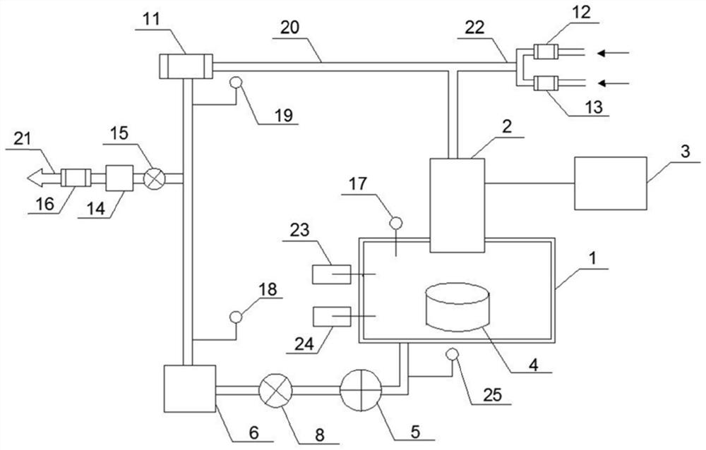
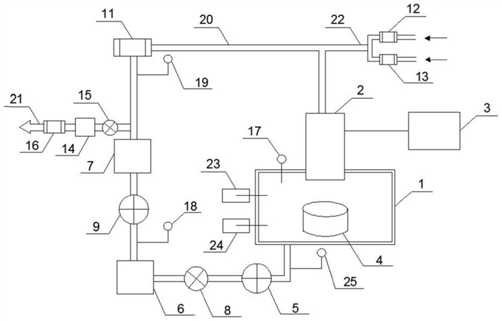
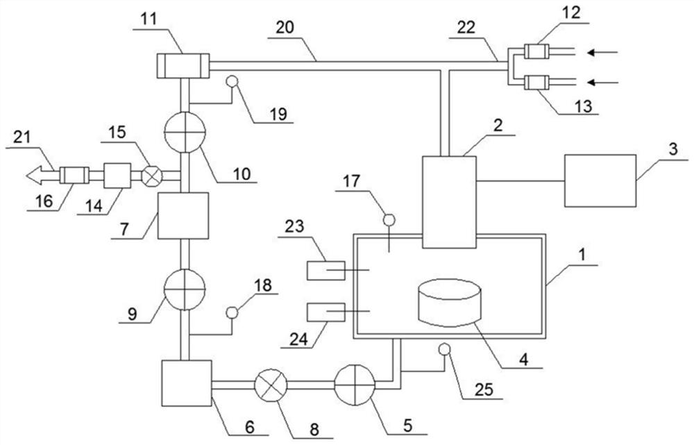
[0143] (1) Use a DC plasma torch with a rated power of 10kW as the heat source, Ar as the auxiliary ionized gas, CH 4 and H 2 It is a reaction gas, which forms plasma after entering the plasma torch 2;

[0144] (2) The formed plasma enters the deposition chamber 1 for plasma chemical vapor deposition, wherein the material of the deposition substrate 4 is molybdenum, and the bottom of the deposition substrate 4 is connected with a water cooling device;

[0145] (3) Vacuum pump unit pumps out the tail gas after the reaction is completed from the deposition chamber 1, and cools down and purifies and removes corrosive gases through the first purification equipment 5, the pumping volume is controlled by the first solenoid valve 8, and the deposition chamber is monitored by the first pressure sensor 17 1, so that the pressure of the deposition chamber 1 is controlled at 80...

Embodiment 2

[0151] The plasma chemical vapor deposition method of the present embodiment comprises the following steps:

[0152] (1) Use the inductively coupled high-frequency plasma torch with rated power of 100kW as the heat source, O 2 , Ar is an ionized gas, gaseous SiCl 4 It is a reaction gas, which forms plasma after entering the plasma torch 2;

[0153] (2) The formed plasma enters the deposition chamber 1 for plasma chemical vapor deposition, wherein the material of the deposition substrate 4 is quartz glass, and the bottom of the deposition substrate 4 is connected with a water cooling device;

[0154] (3) The vacuum pump group takes out the tail gas after the reaction is completed from the deposition chamber 1, and cools down through the first purification equipment 5 and purifies and removes corrosive gases, such as chlorine gas, and is controlled by the first electromagnetic valve 8. The pumping volume, the first pressure sensor 17 Monitor the pressure of the deposition cham...


PUM


Abstract

The invention relates to a plasma chemical vapor deposition system. The deposition system includes a plasma deposition apparatus including a plasma torch and a deposition chamber. The deposition system also includes: a tail gas circulation device, a fresh gas supply device and an online monitoring device, one end of the tail gas circulation device is connected to the exhaust port of the deposition chamber, and the other end is connected to the gas inlet of the plasma torch; the fresh gas supply device , connected to the gas inlet of the plasma torch; the online monitoring device is used for real-time detection of gas composition, temperature, deposition chamber pressure and deposition substrate temperature. The invention also provides a plasma chemical vapor deposition method. The method of the invention recycles the gas discharged from the plasma chemical vapor deposition system after simple treatment, overcomes the problem of large gas consumption in the prior art, greatly reduces gas cost, and ensures the stability of the deposition system at the same time.

Description

technical field [0001] The invention belongs to the field of chemical vapor deposition preparation, in particular to a closed plasma chemical vapor deposition system and method. Background technique [0002] The gas path of traditional plasma chemical vapor deposition system is generally closed inline or semi-open. The closed direct exhaust type is mostly used in low-pressure processes, that is, all production gases, including reaction gases (such as hydrogen, methane, etc.), auxiliary ionized gases (such as argon, oxygen, etc.), enter the plasma torch through a mass flow controller, and then enter the plasma torch through a mass flow controller. Under the action of the arc, the gas is decomposed and ionized, and then sprayed into the deposition chamber to produce a chemical reaction, and the reacted gas is directly discharged out of the deposition system through various methods. In this deposition system, in order to make the plasma arc rotate stably and bring as much ener...

Claims


Application Information

Patent Timeline
Patent Type & Authority Patents(China)
IPC IPC(8): C23C16/513C23C16/455
CPCC23C16/513C23C16/45593
Inventor 孙元成宋学富杜秀蓉张晓强钟利强杨晓会
Owner CHINA BUILDING MATERIALS ACAD
Learn More