
Process method for preventing end pieces of large-scale motor stator core from escaping

A stator core and large-scale motor technology, applied in the direction of motors, manufacturing stator/rotor bodies, electric vehicles, etc., can solve problems such as inability to synchronize thermal expansion and cold contraction, poor bonding effect of end pieces, uneven stress distribution of stators, etc. To achieve the effect of ensuring lasting stability, being easy for enterprises and technical personnel to master, and easy to promote

Active Publication Date: 2020-03-24
HARBIN ELECTRIC MASCH CO LTD
View PDF3 Cites 0 Cited by
  • Summary
  • Abstract
  • Description
  • Claims
  • Application Information

AI Technical Summary

Problems solved by technology

[0002] After the large-scale motor is put into operation, the temperature of the stator core is generally around 70°C, which has a large temperature difference with the surrounding environment. After frequent start-up and shutdown and long-term operation, the stator is too much in a state of thermal expansion and cold contraction , due to the influence of the large temperature difference between the stator punching sheet and the stator frame, the two cannot simultaneously expand and contract with heat and cold, and the internal stress of the stator is unevenly distributed, resulting in a huge interaction force, coupled with the instantaneous impact force of the start-up and shutdown unit and the unit Under the condition of long-term operation and vibration, the bonding effect of the end pieces of the stator core is not good, and loosening occurs, so that the dovetail grooves of the end pieces break free from the control of the positioning ribs, and the stator end pieces move away from the stator core of the motor. The protruding end piece cuts the insulation of the wire rod, causing the winding to ground short-circuit shutdown accident. This phenomenon is especially obvious on large horizontal perfusion units.

Method used


Image

  • Process method for preventing end pieces of large-scale motor stator core from escaping

Examples


Embodiment Construction

[0032] The invention relates to a process method for preventing end pieces from escaping from a stator core of a large motor. The technical solution includes the following steps:

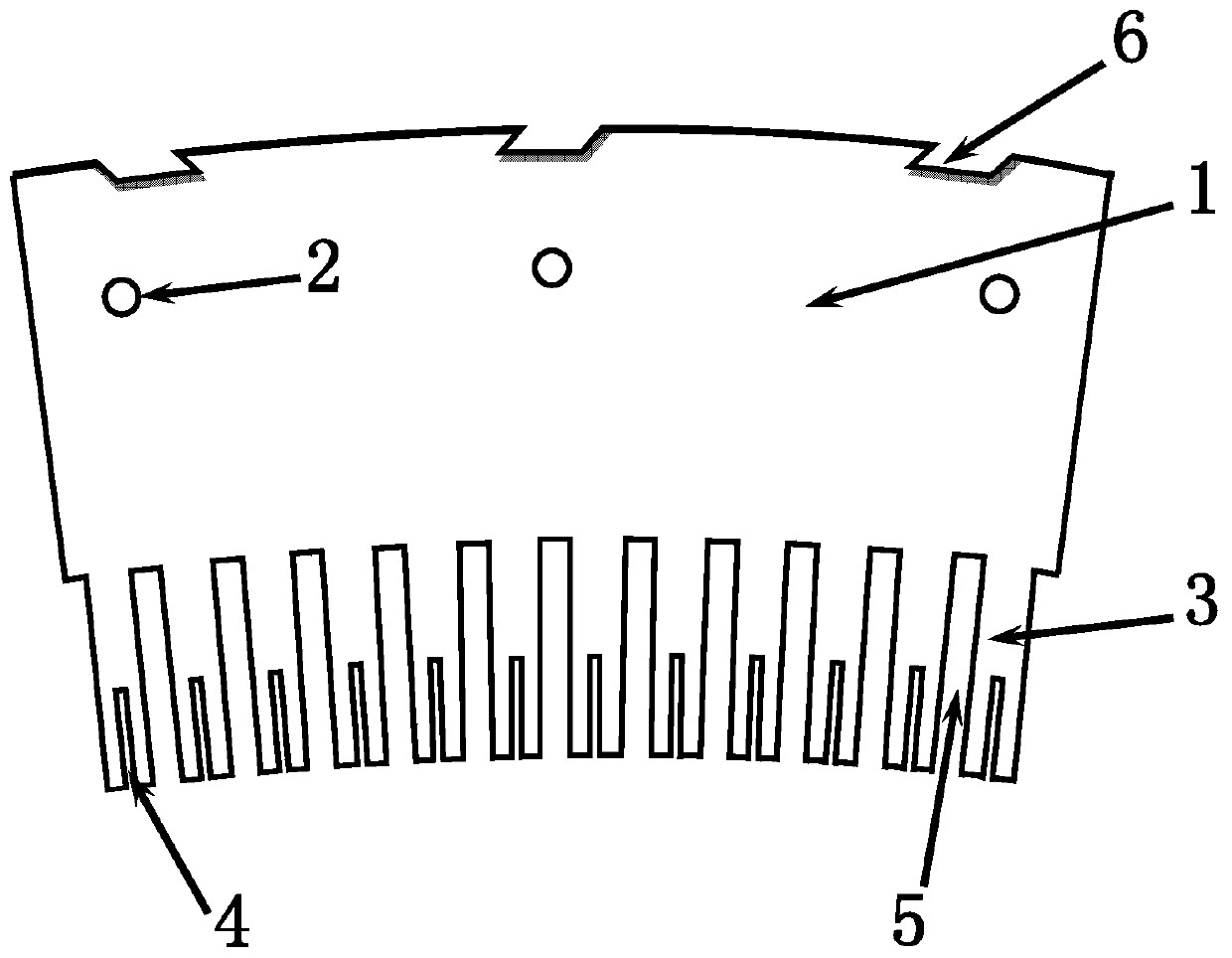
[0033] 1) Auxiliary fixing hole slots and slot size enlargement are added to the end pieces of the stator core: such as figure 1 The stamping piece of the stator core end piece shown in the illustration selects 0.5 mm thick non-oriented silicon steel sheet as the manufacturing material, punches two insulating pin positioning holes 2 with a diameter of 12 mm on the yoke part 1 of the end piece on the punching machine, and punches two insulating pin positioning holes 2 with a diameter of 12 mm for the end piece. Each tooth part 3 is punched with a vertical rib plug groove 4 with a width of 5 mm and a depth of 100 mm. After the end pieces are bonded into a whole, the size of the groove 5 becomes smaller due to the influence of the adhesive film. When processing the size of the groove 5, it is necessary...


PUM


Abstract

The invention discloses a process method for preventing end pieces of a large-scale motor stator core from escaping, which is an innovation of a process method for bonding the end pieces of the large-scale motor stator core, breaks through the conventional bonding mode of silicon steel sheet insulating paint films between the end pieces, and adopts a paint film-free bonding technology between theend pieces. According to the invention, burrs are effectively removed by adopting a surface wire drawing process of the end piece, and the adhesive force of the adhesive on the surface of the end piece is increased. By adopting the technical process of air-drying treatment and vacuum anastomosis bonding after end piece gluing, the phenomenon that bubbles and bulges are generated inside the bondedend pieces is avoided, and the adsorption force between the end pieces is increased. The insulating positioning pins and the vertical rib plug pieces are additionally arranged on the end pieces, so that the integrity of the end pieces is enhanced. According to the invention, the heating phenomenon in the end piece can be effectively detected by adopting a stator core magnetization heating test, and the problem that people cannot detect the quality of internal bonding of the end piece is solved. The method is a novel technical scheme which is high in practicability and easy to popularize.

Description

Technical field: [0001] The invention relates to the field of motors, in particular to a process method for preventing end pieces from escaping from a stator core of a large motor. Background technique: [0002] After the large-scale motor is put into operation, the temperature of the stator core is generally around 70°C, which has a large temperature difference with the surrounding environment. After frequent start-up and shutdown and long-term operation, the stator is too much in a state of thermal expansion and cold contraction , due to the influence of the large temperature difference between the stator punching sheet and the stator frame, the two cannot simultaneously expand and contract with heat and cold, and the internal stress of the stator is unevenly distributed, resulting in a huge interaction force, coupled with the instantaneous impact force of the start-up and shutdown unit and the unit Under the condition of long-term operation and vibration, the bonding effe...

Claims


Application Information

Patent Timeline
Patent Type & Authority Applications(China)
IPC IPC(8): H02K15/02H02K15/10
CPCH02K15/02H02K15/10Y02T10/64
Inventor 王文天王崇光李伟刚王天烁王文彪王景王照森袁外明李英凯
Owner HARBIN ELECTRIC MASCH CO LTD
Learn More