
Distillation recovery device for waste lubricating oil regeneration

A technology for distillation recovery and waste lubricating oil, applied in the field of separation, can solve problems such as being unsuitable for complex waste lubricating oil recovery, affecting the use effect of lubricating oil, and unsuitable for industrialized treatment, so as to achieve recovery, reduce thermal energy consumption, and reduce energy consumption. Effect

Active Publication Date: 2020-03-27
YANTAI LIHENG ENVIRONMENTAL PROTECTION TECH CO LTD
View PDF12 Cites 0 Cited by
  • Summary
  • Abstract
  • Description
  • Claims
  • Application Information

AI Technical Summary

Problems solved by technology

Lubricating oil is used in almost all mechanical equipment. Lubricating oil used for a long time often contains impurities such as moisture, mechanical residues, and carbon deposits, which will affect the use effect of the lubricating oil.
[0003] At present, the devices used for waste lubricating oil recovery are often only for simple filtration or odor removal, which are not suitable for the recovery of complex waste lubricating oil, and are not suitable for industrialized treatment
In reality, the waste lubricating oil often has complex impurity components, and because the lubricating oil used by different machines is often different, the waste lubricating oil is often a mixture of different types of lubricating oil. Distillation recovery device for waste lubricating oil regeneration, which has very important practical value

Method used


Image

  • Distillation recovery device for waste lubricating oil regeneration
  • Distillation recovery device for waste lubricating oil regeneration
  • Distillation recovery device for waste lubricating oil regeneration

Examples


Embodiment Construction

[0036] In order to make the above objects, features and advantages of the present invention more obvious and comprehensible, specific implementations of the present invention will be described in detail below. In the following description, numerous specific details are set forth in order to provide a thorough understanding of the present invention.

[0037] However, the present invention can be implemented in many other ways different from those described here, and those skilled in the art can make similar improvements without departing from the connotation of the present invention, so the present invention is not limited by the specific embodiments disclosed below.

[0038] Unless otherwise defined, all technical and scientific terms used herein have the same meaning as commonly understood by one of ordinary skill in the technical field of the invention. The terminology used herein in the description of the present invention is only for the purpose of describing specific embo...


PUM


Abstract

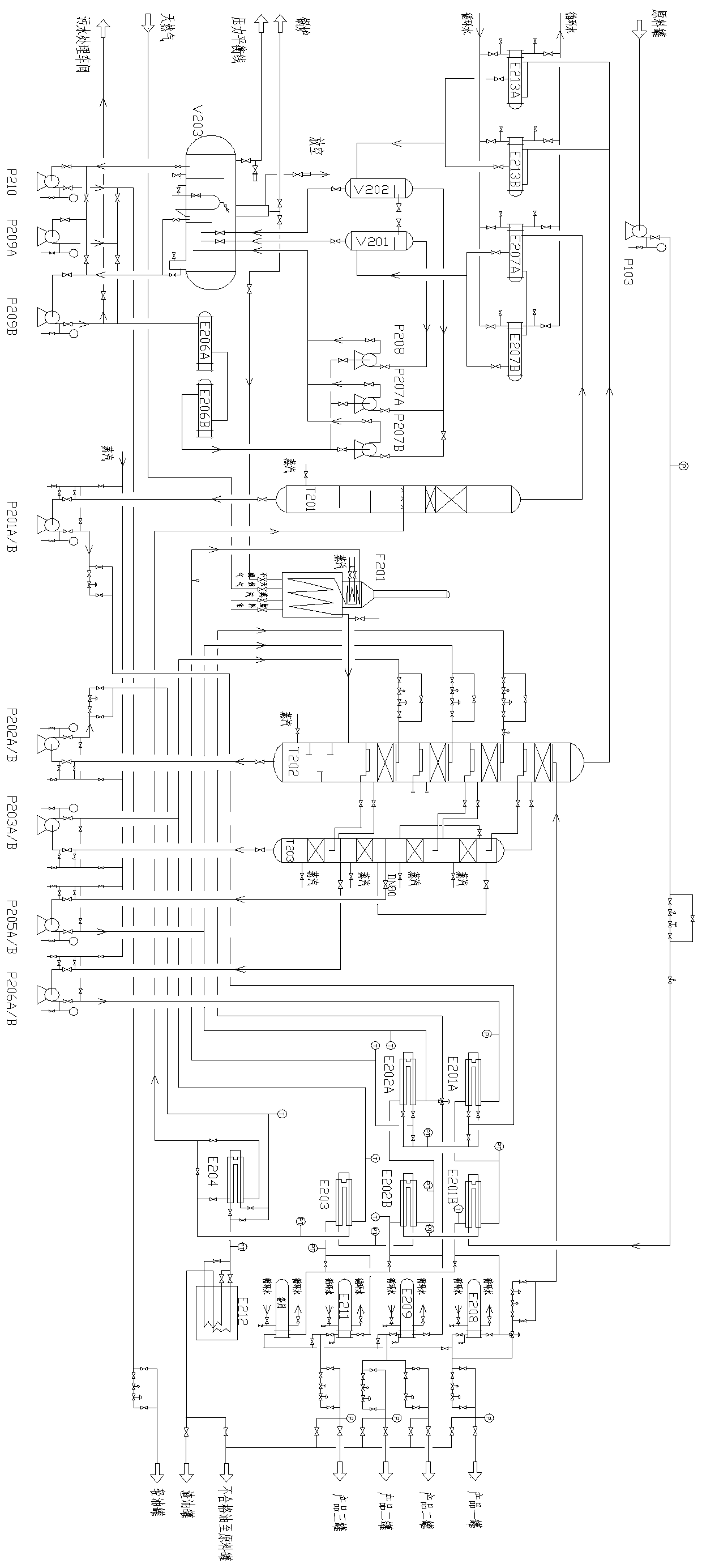
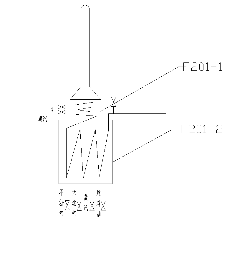
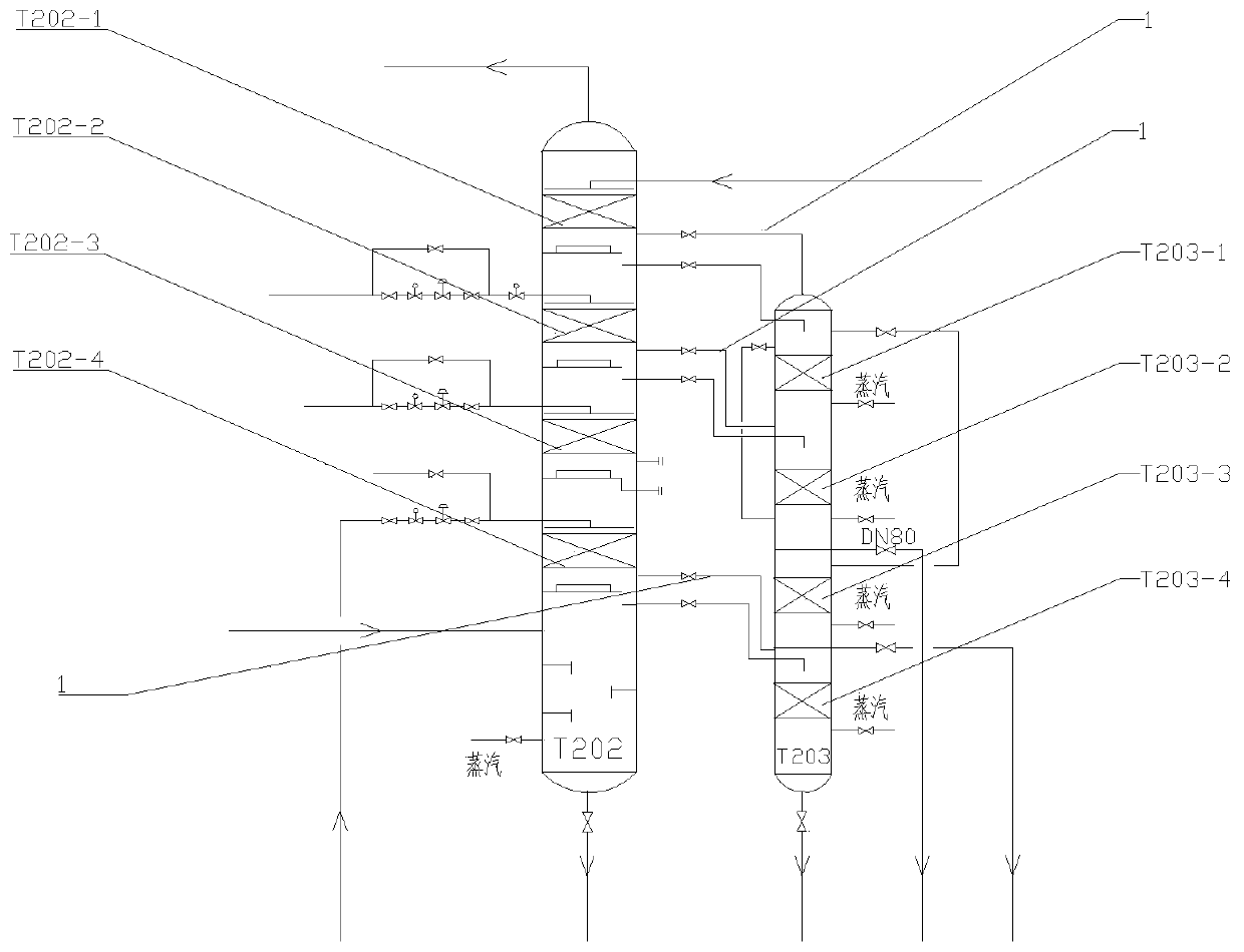
The present invention relates to a distillation recovery device for waste lubricating oil regeneration. The device comprises a raw material tank, a dehydration tower, a heating furnace, a vacuum tower, a stripping tower and an oil-water separator, the raw material tank is connected with a plurality of secondary heat exchangers and a residual oil heat exchanger in series through a raw material oilpump, and the residual oil heat exchanger is connected with the middle of the dehydration tower; the bottom of the dehydration tower is connected with a dehydration bottom pump, the dehydration bottompump is connected with a plurality of primary heat exchangers in series, the primary heat exchangers are connected with the heating furnace, and the heating furnace is connected with the vacuum tower; a multi-line oil collecting tank in the vacuum tower is connected with a multi-line buffer tank in the stripping tower, the multi-line buffer tank is connected with a multi-line transfer pump, the multi-line transfer pump is coupled and connected with the primary heat exchangers and the secondary heat exchangers, the secondary heat exchangers are connected with a pressure reduction cooler, and the pressure reduction cooler is connected with a product tank. The distillation recovery device can achieve recovery of waste lubricating oil with complex components, is low in energy consumption, andis suitable for industrial large-batch treatment.

Description

technical field [0001] The invention relates to a distillation recovery device for regeneration of waste lubricating oil, which belongs to the technical field of separation. Background technique [0002] Lubricating oil is a liquid or semi-solid lubricant used in various types of automobiles and mechanical equipment to reduce friction and protect machinery and processed parts. It mainly plays the roles of lubrication, auxiliary cooling, rust prevention, cleaning, sealing and buffering. Lubricating oil is used in almost all mechanical equipment. Lubricating oil used for a long time often contains impurities such as moisture, mechanical residues, and carbon deposits, which will affect the use effect of the lubricating oil. [0003] At present, the devices used for waste lubricating oil recovery are often only for simple filtration or odor removal, which are not suitable for the recovery of complex waste lubricating oil, and are not suitable for industrialized treatment. In re...

Claims


Application Information

Patent Timeline
IPC IPC(8): C10M175/00
CPCC10M175/00C10M175/0033
Inventor 李玉虎姜伟
Owner YANTAI LIHENG ENVIRONMENTAL PROTECTION TECH CO LTD
Learn More