Clock frequency transmission device capable of resisting optical fiber disturbance

A technology of clock frequency and transmission device, which is applied in the field of optical communication, can solve problems such as the change of optical path group delay, the degradation of phase noise of frequency signal periodic characteristics, and the degradation of transmission phase noise index, and achieve the effect of reducing the degree of sensitivity

Pending Publication Date: 2020-03-27
NO 34 RES INST OF CHINA ELECTRONICS TECH GRP
View PDF0 Cites 1 Cited by
  • Summary
  • Abstract
  • Description
  • Claims
  • Application Information

AI Technical Summary

Problems solved by technology

General-purpose digital optical transmission systems have different time-domain jitter requirements for clocks according to different transmission rates. Some dedicated digital optical transmission systems used in the field of phased array technology not only have jitter requirements for clock signals, but also have high phase noise requirements. Requirements, phase noise refers to the random change of the phase of the output signal caused by the frequency signal under the action of various noises. It is an important indicator to measure the frequency stability of the frequency standard source. The phase noise essentially represents the spectral purity of the frequency signal in the frequency domain. Therefore, it is extremely sensitive to various external interferences. Although optical fiber has natural anti-electromagnetic interference characteristics as a transmission medium, the transmission optical cable will also be affected by various external stresses in the actual environment, causing the microscopic path of the optical signal to change, causing the dispersion value. Changes or changes in the group delay of the optical path, which changes the periodic characteristics of the transmitted frequency signal and causes phase noise degradation
The optical fiber frequency transfer technology currently applied to the timing system generally adopts the direct frequency modulation optical fiber transmission method, mainly focusing on the accuracy of the transmission frequency, and mostly adopts technical means such as optical circuit loopback test and circuit phase compensation to improve the accuracy evaluation of optical line transmission delay , so as to obtain higher time transfer accuracy, there is a large technical bottleneck in both tracking speed and compensation accuracy for the delay change caused by fiber perturbation; while in other multi-static radar optical fiber transmission systems using phased array technology , more attention should be paid to the near-end phase noise index of the frequency signal, which will directly affect the accuracy of radar detection targets. The existing frequency directly modulated optical fiber technology can only be used in the transmission system buried in the entire optical cable, but in reality, generally long-distance In order to reduce the construction cost, the optical transmission system generally adopts the overhead laying method of optical cables, or it will inevitably be affected by various external stresses in the areas of crossing mountains, rivers, and bridges. Stress changes will cause the deterioration of the transmission phase noise index

Method used


Image

  • Clock frequency transmission device capable of resisting optical fiber disturbance
  • Clock frequency transmission device capable of resisting optical fiber disturbance
  • Clock frequency transmission device capable of resisting optical fiber disturbance

Examples


Embodiment

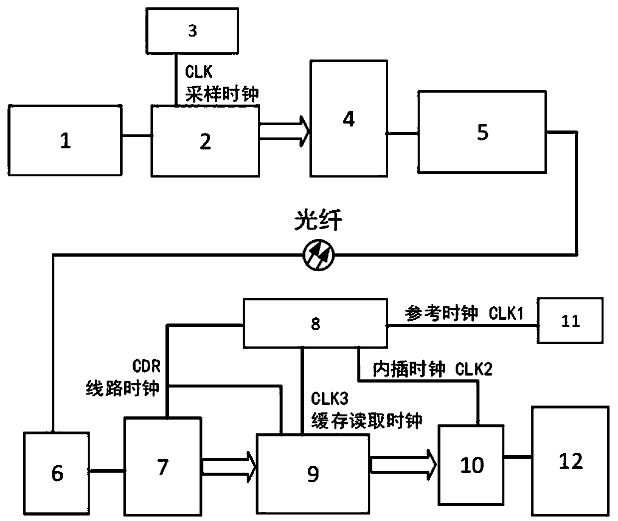
[0030] refer to figure 1 , a kind of anti-optical fiber disturbance clock frequency transmission device, comprising a sending end and a receiving end connected by an optical fiber, the sending end is provided with an input matching unit 1, an analog-to-digital conversion unit 2, a parallel-to-serial conversion unit 4 and a digital Optical modulation unit 5, wherein, analog-to-digital conversion unit 2 is connected to sampling clock source 3, i.e. CLK; the receiving end is provided with sequentially connected digital optical demodulation unit 6, serial-to-parallel conversion unit 7, digital-to-analog conversion unit 9, data storage The buffer unit 10 and the filter amplifying output unit 12, wherein the serial-to-parallel conversion unit 7, the digital-to-analog conversion unit 9 and the data storage buffer unit 10 are all connected to the clock quasi-coherent control output unit 8 connected to the reference clock source 11, namely CLK1.

[0031] The sampling clock source 3, na...


PUM


Abstract

The invention discloses a clock frequency transmission device capable of resisting optical fiber disturbance which is characterized by comprising a sending end and a receiving end which are connectedthrough an optical fiber, the sending end is provided with an input matching unit, an analog-to-digital conversion unit, a parallel-to-serial conversion unit and a digital light modulation unit whichare connected in sequence, and the analog-to-digital conversion unit is connected with a sampling clock source; wherein the receiving end is provided with a digital optical demodulation unit, a serial-parallel conversion unit, a digital-to-analog conversion unit, a data storage buffer unit and a filtering amplification output unit which are connected in sequence, and the serial-parallel conversionunit, the digital-to-analog conversion unit and the data storage buffer unit are all connected with a clock quasi-coherent control output unit connected with a reference clock source. The device is low in cost, low in power consumption, long in transmission distance and flexible to use, and degradation of transmission phase noise indexes caused by optical fiber transmission line disturbance or other external stress changes can be reduced by adopting the device.

Description

technical field [0001] The invention relates to the technical field of optical communication, in particular to a clock frequency transmission device resistant to optical fiber disturbance. Background technique [0002] The clock signal is the benchmark for digital signal processing, control, and communication of modern information products. It realizes normal work between different locations and different devices through the clock synchronization technology of the digital optical transmission system. General-purpose digital optical transmission systems have different time-domain jitter requirements for clocks according to different transmission rates. Some dedicated digital optical transmission systems used in the field of phased array technology not only have jitter requirements for clock signals, but also have high phase noise requirements. Requirements, phase noise refers to the random change of the phase of the output signal caused by the frequency signal under the actio...

Claims


Application Information

Patent Timeline
Patent Type & Authority Applications(China)
IPC IPC(8): H04B10/25H04J3/06
CPCH04J3/0617
Inventor 何翠平熊先越钟昆程鲲覃朝坚袁泉
Owner NO 34 RES INST OF CHINA ELECTRONICS TECH GRP
Why Eureka
Try Eureka