Hydrogenation control device and method

A control method and technology of a control device, which are applied in the directions of adaptive control, container filling method, general control system, etc., can solve the problems of difficulty in realization and communication between vehicles and hydrogen refueling stations, etc. Simple process effect

Pending Publication Date: 2020-03-31
NAT INST OF CLEAN AND LOW CARBON ENERGY
View PDF7 Cites 20 Cited by
  • Summary
  • Abstract
  • Description
  • Claims
  • Application Information

AI Technical Summary

Problems solved by technology

But in reality, because the same vehicle will be refueled at different types of hydrogen refueling stations, and the same hydrogen refueling station will also provide hydrogen refueling services to different types of vehicles, and different types of vehicles or hydrogen refueling stations often have different communication standard, making it difficult to communicate between the vehicle and the hydrogen refueling station
Accordingly, for the situation where the vehicle and the hydrogen refueling station cannot communicate, it is also difficult to realize the solution in the prior art to control the hydrogen refueling rate to adjust the hydrogen temperature based on the real-time feedback temperature or pressure of the on-board hydrogen storage device.

Method used


Image

  • Hydrogenation control device and method
  • Hydrogenation control device and method
  • Hydrogenation control device and method

Examples


Embodiment 1

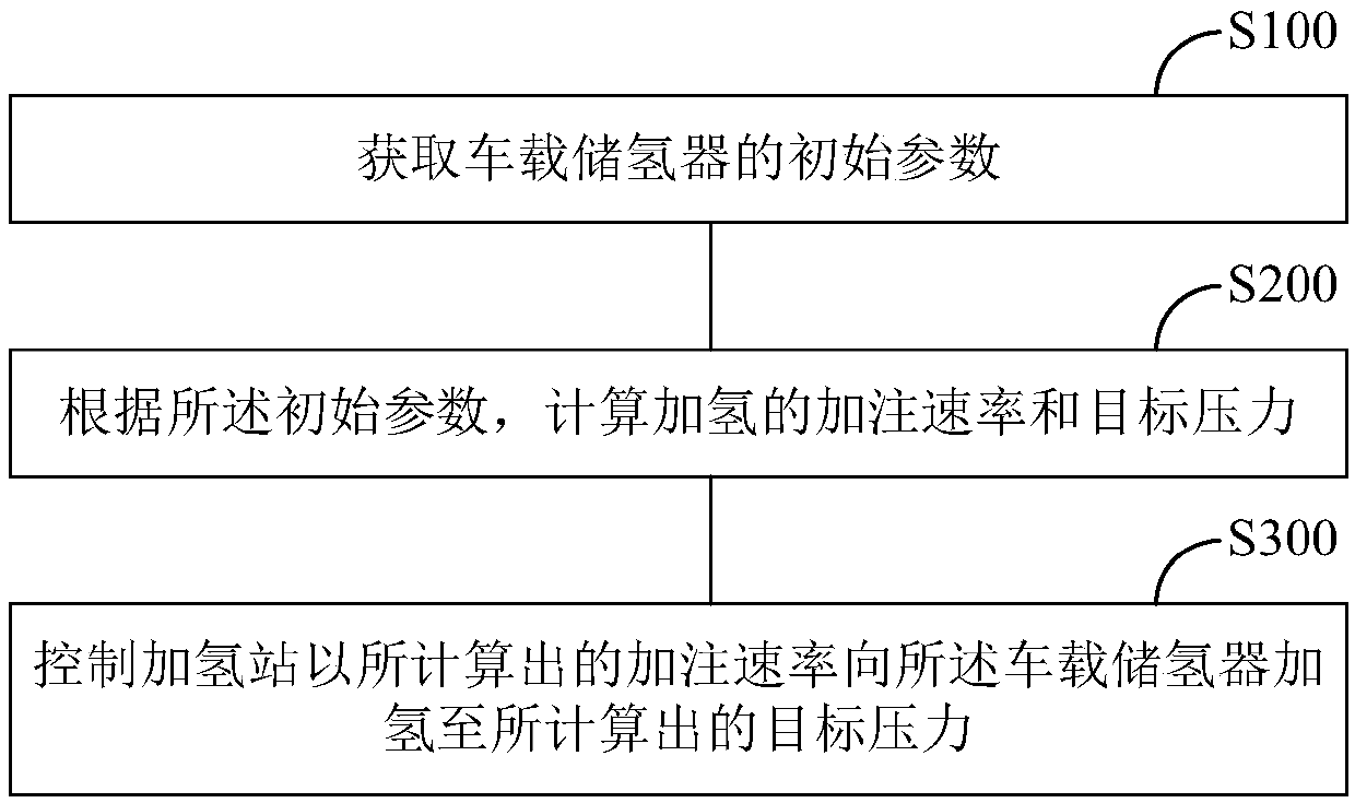
[0039] figure 1 It is a schematic flow chart of the hydrogenation control method in Embodiment 1 of the present invention. Such as figure 1 As shown, the hydrogenation control method may include the following steps:

[0040] Step S100, acquiring the initial parameters of the on-board hydrogen storage device.

[0041] In this embodiment, the initial parameters include the volume of the on-board hydrogen storage device, the initial hydrogen pressure, and the initial ambient temperature, and these three parameters will be described in detail below.

[0042] Regarding the volume of the on-board hydrogen storage device, there are hydrogen storage bottles of various volumes on the market, such as 100L and 200L. However, the volume of the hydrogen storage bottle is usually not considered in the existing hydrogenation process. In order to ensure that the hydrogen temperature does not rise too fast, no matter for a 100L hydrogen storage bottle or a 200L hydrogen storage bottle, the ...

Embodiment 2

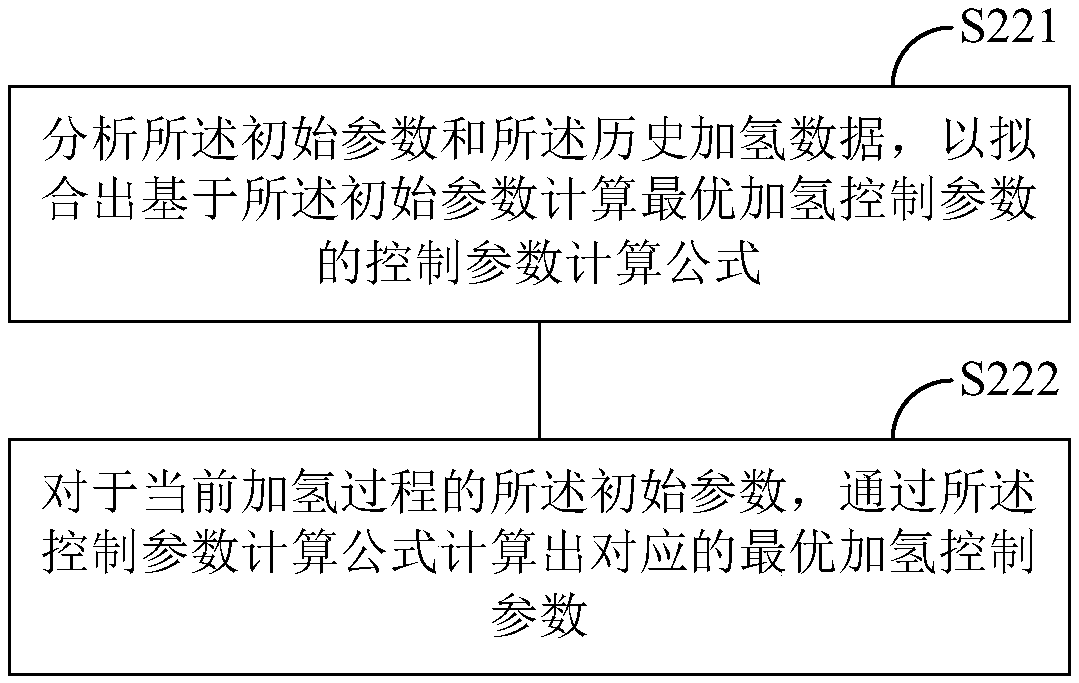
[0065] Compared with the above-mentioned first embodiment, the second embodiment of the present invention mainly differs in the scheme of calculating the filling rate and the target pressure according to the initial parameters in step S200. An embodiment of the present invention provides a formula calculation method to calculate the filling rate and the target pressure according to the initial parameters. in, image 3 It is a schematic flow chart of the formula calculation method of the embodiment of the present invention. Such as image 3 As shown, the formula calculation method may include the following steps:

[0066] Step S221 , analyzing the initial parameters and the historical hydrogenation data to fit a control parameter calculation formula for calculating optimal hydrogenation control parameters based on the initial parameters.

[0067] Wherein, the optimal hydrogenation control parameters include the filling rate and the target pressure.

[0068] For example, the...

Embodiment 3

[0077] Compared with the above two embodiments, the main difference of this third embodiment lies in the scheme of calculating the filling rate and the target pressure according to the initial parameters in step S200. An embodiment of the present invention provides a differential pressure calculation method to calculate the filling rate and the target pressure according to the initial parameters. in, Figure 4It is a schematic flow chart of the differential pressure calculation method of the embodiment of the present invention. Such as Figure 4 As shown, the differential pressure calculation method may include the following steps:

[0078] Step S231 , according to parameters such as the volume of the on-board hydrogen storage device and the ambient temperature, the required filling rate is determined.

[0079] Among them, the values ​​of parameters such as the volume of the on-board hydrogen storage and the ambient temperature can be measured at the hydrogenation machine. ...


PUM


Abstract

The invention provides a hydrogenation control device and method, and belongs to the technical field of hydrogenation. The hydrogenation control method comprises the steps of obtaining the initial parameters of a vehicle-mounted hydrogen storage device, wherein the initial parameters comprise the volume of the vehicle-mounted hydrogen storage device, initial hydrogen pressure and initial environment temperature; according to the initial parameters, calculating the filling rate and target pressure of hydrogenation, wherein the calculated filling rate and target pressure enable the hydrogen temperature in the hydrogenation pressure to be in a preset safety range; and controlling a hydrogenation station to hydrogenate the vehicle-mounted hydrogen storage device to the calculated target pressure at the calculated filling rate. The hydrogenation control device and method do not need the real-time communication between the hydrogenation station and a vehicle, and controls the filling processby obtaining the filling rate and the target pressure through the initial parameters of the vehicle-mounted hydrogen storage device measured by the hydrogenation station. The process is simple and easy to implement, and the reliability of hydrogenation process is ensured.

Description

technical field [0001] The invention relates to the technical field of hydrogenation, in particular to a hydrogenation control device and method. Background technique [0002] Hydrogen energy is considered to be one of the most promising secondary energy sources due to its outstanding advantages such as diverse sources, clean environmental protection, and large-scale storage and transportation. Hydrogen fuel cell vehicles are one of the important application terminals of hydrogen energy. Many auto giants in the world have launched mass-produced hydrogen fuel cell vehicles around 2015. At present, the research on hydrogen fuel cell vehicles is multifaceted, but the filling control strategy of the hydrogenation station to the on-board hydrogen storage (hereinafter referred to as the hydrogenation control strategy) is undoubtedly one of the focuses of research at home and abroad. [0003] One of the technical problems that the existing hydrogen refueling control strategy mainl...

Claims


Application Information

Patent Timeline
Patent Type & Authority Applications(China)
IPC IPC(8): F17C5/06F17C13/00F17C13/02
CPCF17C5/06F17C13/00F17C13/003F17C13/02F17C13/025F17C13/026F17C2221/012F17C2265/061Y02E60/32F17C2270/0139F17C2265/065F17C5/007F17C2223/0123F17C2223/036F17C2225/0123F17C2225/036F17C2250/032F17C2250/043F17C2250/0434F17C2250/0426F17C2250/0631F17C2250/0626F17C2250/0636F17C2250/0694F17C2250/075F17C2260/023F17C2250/0439F17C2205/05F17C2270/0178F17C2270/0184F17C2260/042F17C13/028G05B13/042
Inventor 何广利杨康郭强范玉建许壮
Owner NAT INST OF CLEAN AND LOW CARBON ENERGY
Why Eureka
Try Eureka