
Air drying equipment for wig fibers

A fiber and equipment technology, applied in the field of wig fiber air-drying equipment, can solve the problems of uneven drying effect, large investment in equipment, and hair damage, etc., to achieve the effect of improving drying effect, improving drying efficiency, and avoiding hair breakage

Pending Publication Date: 2020-03-31
禹州市金博发制品有限公司
View PDF0 Cites 4 Cited by
  • Summary
  • Abstract
  • Description
  • Claims
  • Application Information

AI Technical Summary

Problems solved by technology

The hair that has been subjected to high-temperature styling in a water tank needs to be further dried and stored. The existing drying method is slow to dry, requires a large investment in equipment, and the drying effect is not uniform enough, which is easy to cause damage to the hair during the drying process. Therefore, a new type of drying method is needed. wig fiber drying equipment

Method used


Image

  • Air drying equipment for wig fibers
  • Air drying equipment for wig fibers
  • Air drying equipment for wig fibers

Examples


Embodiment 1

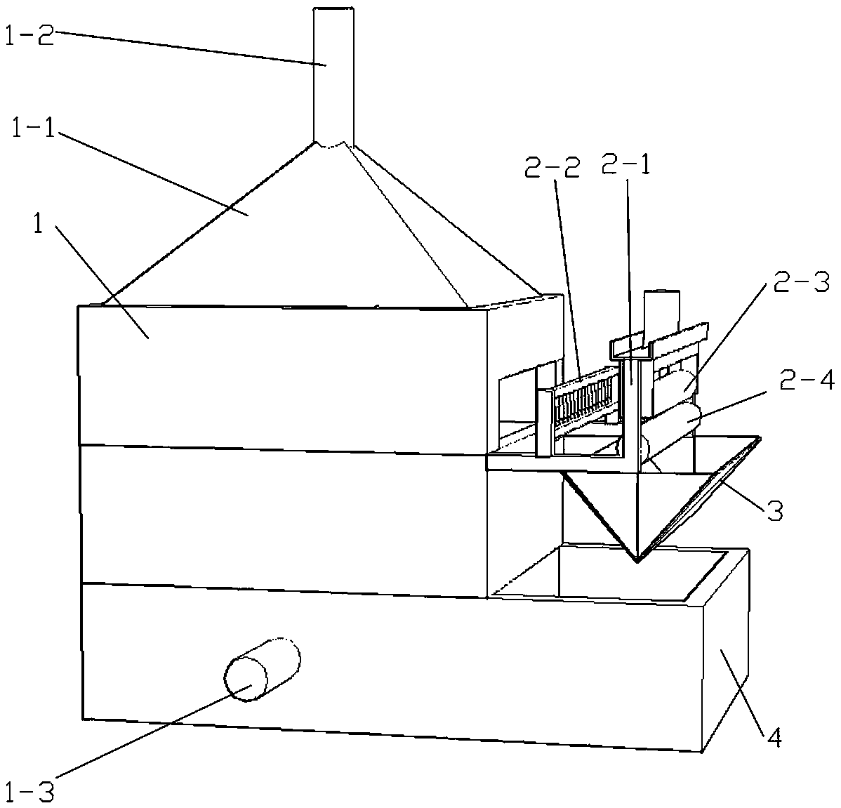
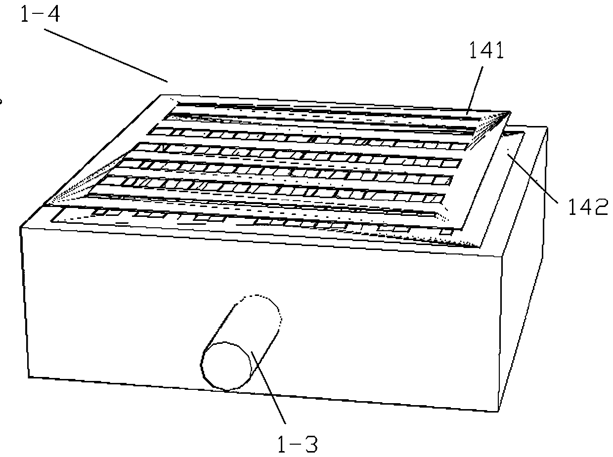
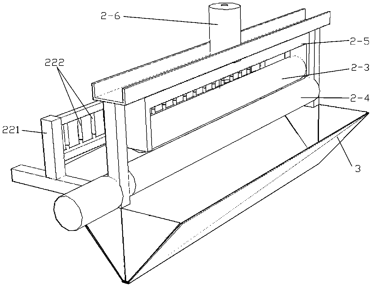
[0022] As shown in the figure, the embodiment of the present invention provides an air-drying device for wig fibers, including a bellows 1, the bellows 1 is a rectangular cabinet structure as a whole, and an exhaust chamber 1-1 is arranged on the top of the cabinet. The exhaust chamber 1-1 communicates with the outside through the exhaust pipe 1-2, openings for hair passing are provided on the two opposite side walls of the bellows 1, and an air inlet is provided at the lower section of the side of the bellows 1. The pipe 1-3 is provided with a hair dispersing assembly 2 at the hair inlet of the bellows 1, and the hair dispersing assembly 2 includes a mounting frame 2-1, a squeeze roller assembly and a hair dispersing row 2-2, the The hairline dispersing row 2-2 includes a rectangular frame 221 and partition bars 222 sequentially distributed in the rectangular frame 221. Each partition bar 222 is arranged vertically and arranged horizontally in sequence. A drum is sheathed on ...

Embodiment 2

[0025]As shown in the figure, the embodiment of the present invention provides a styling and air-drying device for wig fibers and a hair preparation method. The styling and air-drying device includes a styling device and an air-drying device. The air-drying device includes a bellows 1. It is a cuboid cabinet structure, and an exhaust cavity 1-1 is arranged on the top of the cabinet, and the exhaust cavity 1-1 communicates with the outside through the exhaust pipe 1-2, corresponding to the two opposite side walls of the bellows 1. An opening for hair to pass through is provided, an air inlet pipe 1-3 is arranged at the lower section of the side of the bellows 1, and a hair dispersing assembly 2 is provided at the hair inlet of the bellows 1, and the hair dispersing assembly 2 includes an installation Frame 2-1, extruding roller assembly and hairline dispersion row 2-2, described hairline dispersion row 2-2 comprises rectangular frame 221 and divider bar 222 that is distributed i...


PUM


Abstract

The invention discloses air drying equipment for wig fibers. A wind box is included. The whole wind box is a cuboid cabinet body structure. An exhaust cavity is arranged in a top of a cabinet body. The exhaust cavity is connected with the outside world through an air exhaust pipe. Openings for hair to penetrate through are correspondingly arranged in two opposite side walls of the wind box. An airinlet pipe is arranged at a lower section of a side surface of the wind box. A hair dispersion component is arranged at a hair inlet of the wind box. The hair dispersion component comprises an installation frame, an extrusion roller component and a hair dispersion row. The extrusion roller component and the hair dispersion row are arranged on the installation frame. The extrusion roller componentis rotatably arranged on an outer side of the hair dispersion row, the extrusion roller component is used for extruding moisture in hair and comprises an upper extrusion roller and a lower extrusionroller, and a driving motor is installed at one end of the lower extrusion roller. The device is uniform in drying effect, the hair cannot be damaged, and operation efficiency can be effectively improved.

Description

technical field [0001] The invention belongs to the technical field of wig fiber preparation, and in particular relates to an air-drying device for wig fiber. Background technique [0002] Chinese people have long had the habit of wearing wigs. At first, they were ornaments for women in the upper class. They were added to the original hair to make it thicker and make it into a bun. Wigs were popular in the Spring and Autumn Period. In the Han Dynasty, hairstyles and hair accessories were formulated according to "Zhou Li". There are many styles. [0003] In recent years, with the continuous improvement of the quality of life, people's consumption on clothing has also increased year by year. As one of the cosmetics for beauty lovers, wigs are used more and more. The use of chemical fiber as a new raw material in the hair product industry has attracted more and more people's attention and attention, and the products are gradually showing a trend of diversification. Different...

Claims


Application Information

Patent Timeline
Patent Type & Authority Applications(China)
IPC IPC(8): F26B13/28F26B13/10F26B21/00F26B25/00
CPCF26B13/28F26B13/108F26B21/004F26B25/003
Inventor 张亚超
Owner 禹州市金博发制品有限公司
Learn More