Supercharge Your Innovation With Domain-Expert AI Agents!

Undervoltage protection circuit and its control method

An under-voltage protection and circuit technology, applied in emergency protection circuit devices, protections that respond to under-voltage or no-voltage, circuit devices, etc. Abnormal and other problems, to achieve the effect of accurate hysteresis voltage, accurate turn-on voltage, and reduced loss

Active Publication Date: 2022-02-18
MORNSUN GUANGZHOU SCI & TECH
View PDF4 Cites 0 Cited by
  • Summary
  • Abstract
  • Description
  • Claims
  • Application Information

AI Technical Summary

Problems solved by technology

[0015] In view of this, the present invention aims to solve the above-mentioned problems such as large loss of the undervoltage protection circuit, inaccurate control voltage, restart of the product, abnormal operation of the comparator, etc.

Method used


Image

  • Undervoltage protection circuit and its control method
  • Undervoltage protection circuit and its control method
  • Undervoltage protection circuit and its control method

Examples


no. 1 example

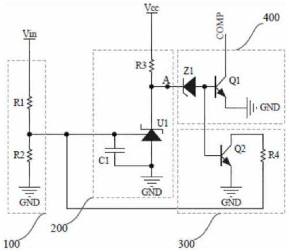
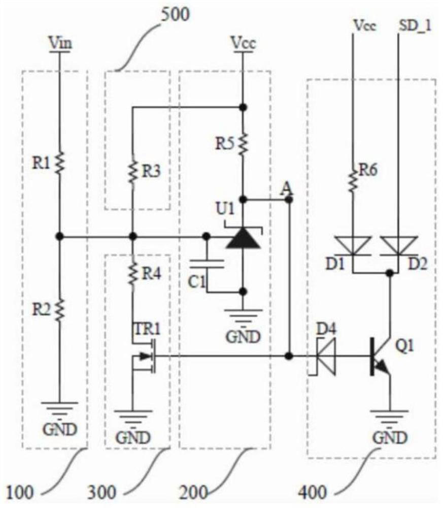
[0041] image 3 It is the circuit principle diagram of the undervoltage protection circuit of the first embodiment of the present invention, image 3 Shown the present invention scheme and figure 1 Existing undervoltage protection circuit diagram, figure 2 The difference of the circuit scheme shown in the existing patent 201610101819.6 undervoltage protection circuit diagram is that the voltage at both ends of the resistor R4 is used as the input of the switch circuit, the cathode of the Zener diode D1 is connected to Vcc, the anode of the Zener diode D1 is connected to the emitter of the PNP transistor Q1, and the output The control is to enable the EN pin of the chip, add diode D2 and resistor R6.

[0042] Embodiments of the invention will be described in detail below in conjunction with the accompanying drawings.

[0043] An undervoltage protection circuit includes: a sampling circuit, a control circuit, a switch circuit and a hysteresis circuit.

[0044] The sampling ...

no. 2 example

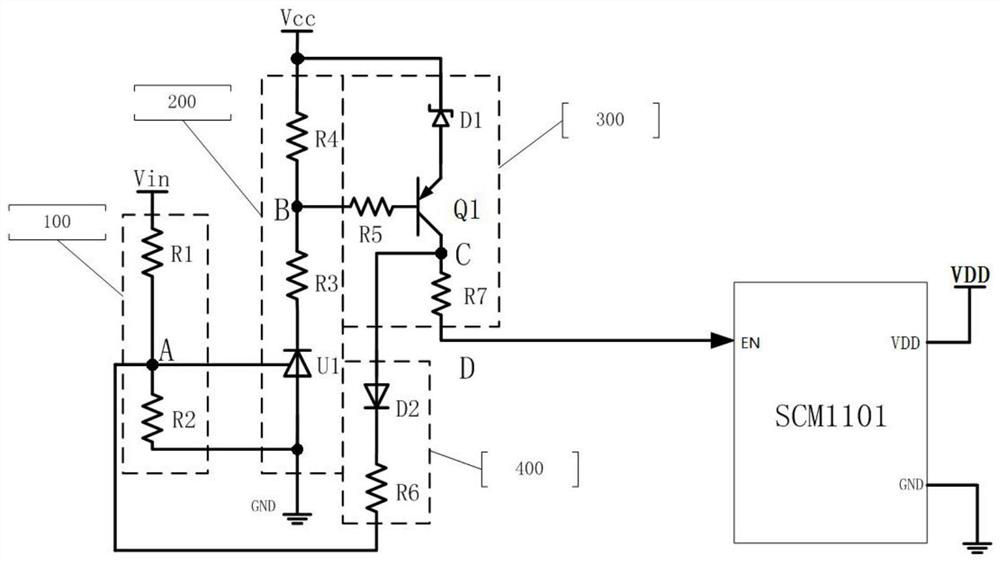
[0065] like Image 6 As shown, the second implementation of the present invention is based on the first embodiment, adding a resistor R8 to the switch circuit, one end of the resistor R8 is connected to the resistor R7, and the other end is grounded to GND. Resistor R7 and resistor R8 divide the voltage. The connection point of R7 and R8 is used as the input of the voltage type control chip, and the voltage control type enable EN is realized by setting the voltage division ratio of the resistors R7 and R8.


PUM


Abstract

The invention discloses an undervoltage protection circuit, which includes a sampling circuit 100, a control circuit 200, a switch circuit 300, and a hysteresis circuit 400; The input circuit is connected in series with the Zener diode D1 to reduce the loss of the undervoltage protection circuit; the collector of the PNP triode is connected in series with the diode D2 and the resistor R6 to form a stable, accurate and easy-to-adjust hysteresis voltage. Adoption of the present invention has the advantages of accurate on-off control of the undervoltage protection circuit, reduced loss, accurate and easy adjustment of the hysteresis voltage, thereby improving the overall reliability of the applied circuit.

Description

technical field [0001] The invention relates to a switching power supply, in particular to an undervoltage protection circuit of the switching power supply and a control method thereof. Background technique [0002] Most of the existing electronic products, such as: DC / DC converters, etc., all need undervoltage protection circuits to avoid problems such as damage to electronic products caused by entering an abnormal working state when the input voltage is too low. [0003] figure 1 For the existing undervoltage protection circuit diagram, figure 1 The sampling circuit 100 of the undervoltage protection circuit samples the input voltage Vin and then outputs a sampling signal, and then inputs the sampling signal to the reference pin of the TL431 of the control circuit 200, and the TL431 outputs a control signal according to the sampling signal to the hysteresis circuit through the Zener diode Z1 The switching tube Q2 of 300 and the switching tube Q1 of the switching circuit;...

Claims


Application Information

Patent Timeline
Patent Type & Authority Patents(China)
IPC IPC(8): H02H3/24H02H3/00
CPCH02H3/24H02H3/006
Inventor 李鑫坤尹显泓刘杰
Owner MORNSUN GUANGZHOU SCI & TECH
Features
  • R&D
  • Intellectual Property
  • Life Sciences
  • Materials
  • Tech Scout
  • Unparalleled Data Quality
  • Higher Quality Content
  • 60% Fewer Hallucinations
Learn More