
Pulse modulator

A pulse modulator and pulse technology, applied in the high voltage field, can solve the problems of unreasonable structure layout, huge volume and weight, and many discrete components, and achieve the effect of light weight, reduced volume and weight, and small volume

Pending Publication Date: 2020-03-31
陕西中控微脉智能科技有限公司
View PDF0 Cites 4 Cited by
  • Summary
  • Abstract
  • Description
  • Claims
  • Application Information

AI Technical Summary

Problems solved by technology

[0004] Faced with the above technical background, the present invention proposes a miniaturized high-voltage large-scale Current pulse modulator, by optimizing the internal circuit structure and systematically integrating integrated components, realizes the miniaturization and compactness of high-voltage and high-current pulse modulators in engineering, laying the foundation for practical applications in multiple fields and occasions

Method used


Image

  • Pulse modulator
  • Pulse modulator
  • Pulse modulator

Examples


Embodiment 1

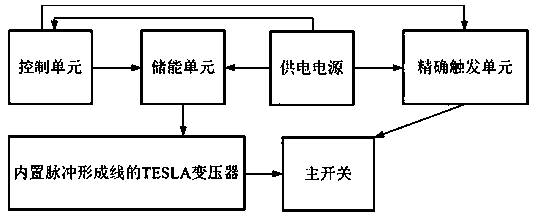
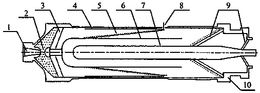
[0028] Such as figure 1 with figure 2 As shown, a pulse modulator includes a power supply, a control unit, an energy storage unit, a TESLA transformer with a built-in pulse forming line, a main switch and an accurate trigger unit. Among them, the power supply provides electric energy to units such as the control unit, the energy storage unit and the precise trigger unit. The control unit completes the timing triggering, status monitoring, energy supplement, logic management, emergency management, fault detection and other functions of the whole system. The control unit is composed of existing FPGA and peripheral circuits, including A / D and D / A interfaces, optical fiber Interface, etc., the energy storage unit completes the storage of electric energy and the first level of energy compression, the TESLA transformer with built-in pulse forming line plays the role of pulse boosting and energy transmission, the main switch completes the second level of energy compression, and the...

Embodiment 2

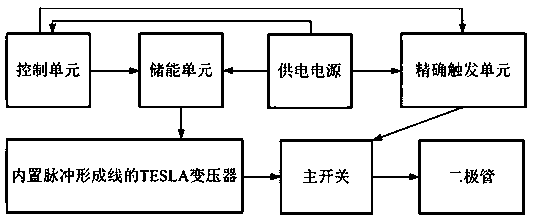
[0038] On the basis of Embodiment 1, a diode is added, such as image 3 and Figure 4 As shown, the diode 11 is arranged at the other end of the packaging shell 10, and the diode 11 is connected to the inner cylinder 7 of the pulse forming line. In this solution, the diode is the high-voltage and high-current pulse output port of the entire modulator.

[0039] For the pulse modulator described in Embodiment 1 and Embodiment 2, its typical output parameters are as follows Figure 5 As shown, the miniaturized high-voltage and high-current pulse modulator proposed by the present invention can produce a voltage ranging from 100,000 volts to 500,000 volts, and an electric power of about 1 GW to 5 GW (1 GW=10 9 watts) of electrical impulse. The electrical pulse width is between 2 nanoseconds and 50 nanoseconds (1 nanosecond = 10 -9 seconds). The working mode of the miniaturized high-voltage and high-current pulse modulator is a pulse train type, that is, a limited number of elec...


PUM


Abstract

The invention provides a pulse modulator, belonging to the technical field of high voltage, the pulse modulator comprises a power supply, a control unit, an energy storage unit, an accurate triggeringunit and a TESLA transformer with a built-in pulse forming line, and a main switch, and a diode. The energy storage unit is used for electric energy storage and first-stage energy compression, the TESLA transformer with the built-in pulse forming line is used for pulse boosting and energy transmission, and the main switch is used for second-stage energy compression. By optimizing the internal circuit structure and systematically integrating integrated components, the pulse modulator has the advantages of being small in number of separated components, small in size, light in weight and the like, miniaturization and compactness of the high-voltage large-current pulse modulator are truly achieved in engineering, and a foundation is laid for practical application in multiple fields and occasions.

Description

Technical field [0001] The invention relates to a pulse modulator, which belongs to the field of high voltage technology, and particularly refers to a miniaturized high-voltage and high-current pulse modulator. The application scope includes but is not limited to: high-voltage pulse generation, microwave generation, X-ray generation, biomedicine, and materials. treatment, environmental protection treatment, environmental governance, facility agriculture and other fields. Background technique [0002] High-voltage technology, especially instantaneous high-voltage technology, is a technology that stores low-voltage, low-power electrical energy and generates ultra-high voltage through boost conversion and instantaneous compression. The high-voltage and high-current pulse modulator is an important high-voltage generating device, with an output voltage of hundreds of thousands of volts and a current of several thousand amperes. At present, high-voltage and high-current pulse mod...

Claims


Application Information

Patent Timeline
Patent Type & Authority Applications(China)
IPC IPC(8): H03K7/06
CPCH03K7/06
Inventor 陈炎伟李伟李立明
Owner 陕西中控微脉智能科技有限公司
Learn More