Laser welding tinning device and welding method

A laser welding and laser position technology, applied in tin feeding devices, auxiliary devices, welding equipment, etc., can solve the problem of bending or offset, can not accurately judge the contact force between the tin wire and the solder joint, can not accurately judge the tin wire and welding Points and other issues to achieve the effect of compensating for the effect of the welding effect

Active Publication Date: 2020-04-07
WUHAN BESKYS TECH CO LTD
View PDF8 Cites 8 Cited by
  • Summary
  • Abstract
  • Description
  • Claims
  • Application Information

AI Technical Summary

Problems solved by technology

[0003] The Chinese utility model patent "Laser soldering device for automatic calibration and tin feeding" (201820105083.4) uses a laser emitter and the first CCD component, etc., which are used to melt the tin wire for welding and obtain the image information of the tin wire; and then obtain the image information of the tin wire The protruding length, the deviation between the tin wire and the laser spot, and the appearance information of the tin wire; then use the control laser emitter and the tin feeding component to trim the tin wire to solve the problem of tin feeding amount control and automatic correction. The problem is that the device cannot accurately determine the contact force between the tin wire and the solder joint; the Chinese invention patent "A Tin Wire Precision Welding Device and Control Method" (201710413205.6) is based on two sets of vision systems that collect three-dimensional images of tin wire. By comparing the length, position and attitude of the tin wire at the initial and detection times and obtaining the deviation, and then using the laser tin cutting process, automatic tin scraping process and automatic tin wire pushing method, the solder ball, bending, and

Method used


Image

  • Laser welding tinning device and welding method
  • Laser welding tinning device and welding method
  • Laser welding tinning device and welding method

Examples


Embodiment 1

[0084] Embodiment 1: SMD welding

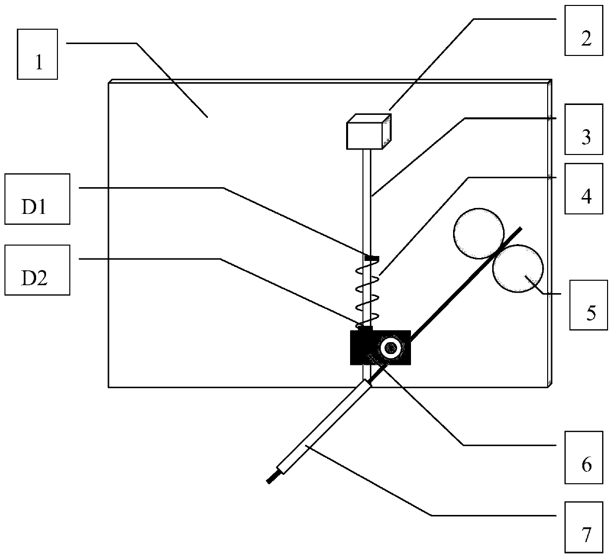
[0085] refer to Figure 4 with Figure 5 , it is necessary to ensure that the tin wire is in good contact with the solder joint during patch welding, that is, the contact force f is always kept at f during the welding process 0 , f 0 It can be selected according to the characteristics of tin wire and welding process. In the positioning stage, when the contact force between the tin wire and the pad is at f b When within the range of ±Δf, stop positioning immediately. During the welding process, the pushing speed of the tin wire is adjusted by the PID algorithm. When the tin tip is not melted, if the tin is continuously fed, the contact force f between the tin wire and the pad will increase, and the tin feeding speed should be reduced at this time; When the wire melts too fast, the contact force f between the tin wire and the pad decreases, and the tin feeding speed should be accelerated at this time.

Embodiment 2

[0086] Embodiment 2: pin welding

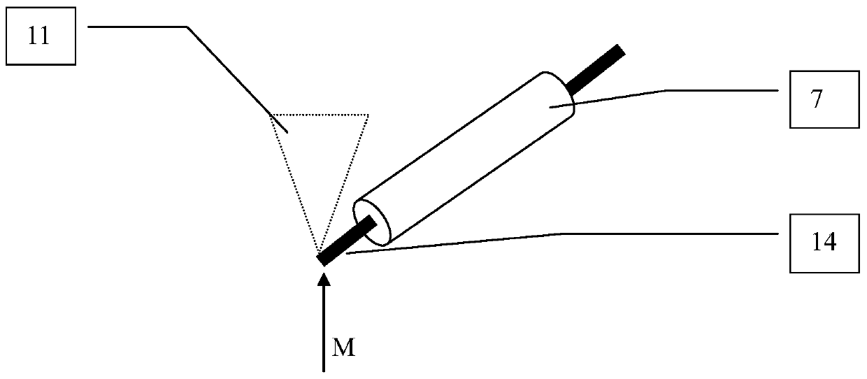
[0087] refer to Figure 4 with Image 6 , when the pin pin 15 is deformed, in the positioning stage of the probe head 14, the tin tip 16 will be deflected to the right after contacting the top of the pin 15, and the angle sensor 2 records the deflection angle of the tin wire 14, but at this time the balance spring 4 The vertical contact force is 0, so the device continues to move downward. During the movement, under the restoring force of the balance spring 4, the tin tip 16 is always in contact with the contact pin 15 until the contact force f is within f b within the range of ±Δf. During the contact process between the tin tip 16 and the contact pin 15, the running track of the tin tip 16 is close to the shape of the contact pin 15, such as Image 6 As shown, the tin tip 16 can effectively avoid the interference of the pin pin 15 and be accurately positioned to the pad 8 to be soldered.

[0088] The invention utilizes the position feed...


PUM


Abstract

The invention designs a laser welding tinning device and a welding method. The tinning device comprises a back plate, a laser position correcting device, a camera, a laser machining head, a pushing wheel pair, a connecting rod, a tin feeding nozzle, a displacement sensor, an angle sensor, a balance spring, a controller and a residue box, wherein the angle sensor detects a swing angle of the connecting rod, the displacement sensor detects the vertical movement position of the connecting rod, the controller calculates the movement speed and the acceleration of the detection head according to thedisplacement amount and an angle change value of the detection head, during laser welding, laser working height closed-loop control is carried out by utilizing the position of the detection head, tinwire feeding speed closed-loop control is carried out by utilizing stress of the detection head, and closed-loop control that laser follows the position of a tin wire is carried out by utilizing theangle of the detection head, influence of the welding spot height difference on the welding effect can be made up, the product machining fixing requirement is lowered, and the application range of laser welding is expanded. The tinning device is advantaged in that mechanical collision or burning of a processing base material can be prevented, the process is stable, and the qualified rate is improved.

Description

technical field [0001] The invention relates to a tinning device for laser welding and a welding method, in particular to a tinning device for laser tin wire welding and a welding method using the device, belonging to the technical field of laser tin wire welding. Background technique [0002] In the field of fine processing of laser tin wire welding, as the requirements of production technology become higher and higher, the conditions of use of processing equipment are becoming more and more stringent. Existing traditional equipment often cannot meet the requirements of emerging technologies. For example, when laser welding specific tiny solder joints, a slight deviation between the laser and the tin wire or the solder joints will cause the solder joints to burn or the substrate to be scrapped. The difference between laser soldering and traditional electric soldering iron welding is that there is no contact force directly acting on the solder joint during laser welding. If ...

Claims


Application Information

Patent Timeline
IPC IPC(8): B23K3/06B23K3/08B23K1/005
CPCB23K1/0056B23K3/063B23K3/08
Inventor 王浩徐琦邱浩波叶凯蔡仁树李仁明
Owner WUHAN BESKYS TECH CO LTD
Why Eureka
Try Eureka