Activated sludge cracking and separating integrated device and process

A technology of activated sludge and plasma, applied in sludge treatment, pyrolysis sludge treatment, electrochemical sludge treatment, etc., can solve the problems of limited recovery rate, long reaction time, unstable performance, etc., and achieve the reduction of gas-solid Effects of load separation, high chain reaction rate, and low energy consumption for reaction triggering

Pending Publication Date: 2020-04-10
葛洲坝水务淄博博山有限公司 +1
View PDF0 Cites 0 Cited by
  • Summary
  • Abstract
  • Description
  • Claims
  • Application Information

AI Technical Summary

Problems solved by technology

[0005] Plasma material treatment has low pretreatment efficiency, high plasma energy consumption, unstable performance, especially high requirements for moisture content control
Simple plasma treatment requires high equipment energy consumption, serious waste of sensible heat, and heat energy recovery efficiency limits the level of energy consumption utilization; high-temperature plasma treatment needs to add auxiliary carbon sources, and low-temperature plasma technology has poor solid-liquid separation effect
[0006] Other sludge disposal methods, such as low-temperature drying, require large equipment volume, difficult heat insulation, high heat loss; long reaction time, large equipment volume; multiple heat recovery, many equipment, heat recovery limit limits recovery rate
In terms of activated sludge carbon source recycling, existing technologies such as low-temperature drying and anaerobic oxidation have deficiencies in microbial inactivation, heavy metal mineralization, and phosphate mineralization.

Method used


Image

  • Activated sludge cracking and separating integrated device and process
  • Activated sludge cracking and separating integrated device and process
  • Activated sludge cracking and separating integrated device and process

Examples


Embodiment Construction

[0050] The present invention will be described in further detail below in conjunction with the accompanying drawings and specific embodiments, so that those skilled in the art can understand.

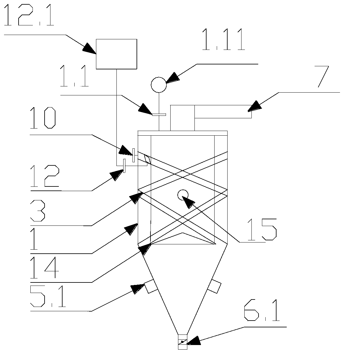
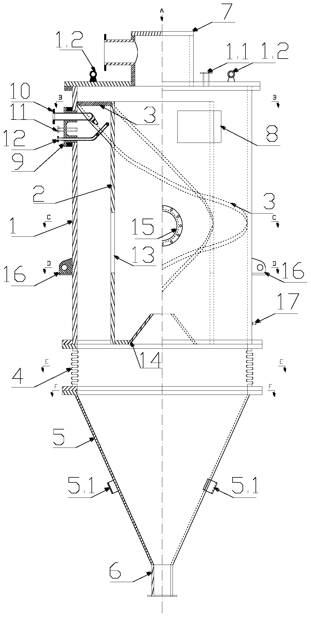
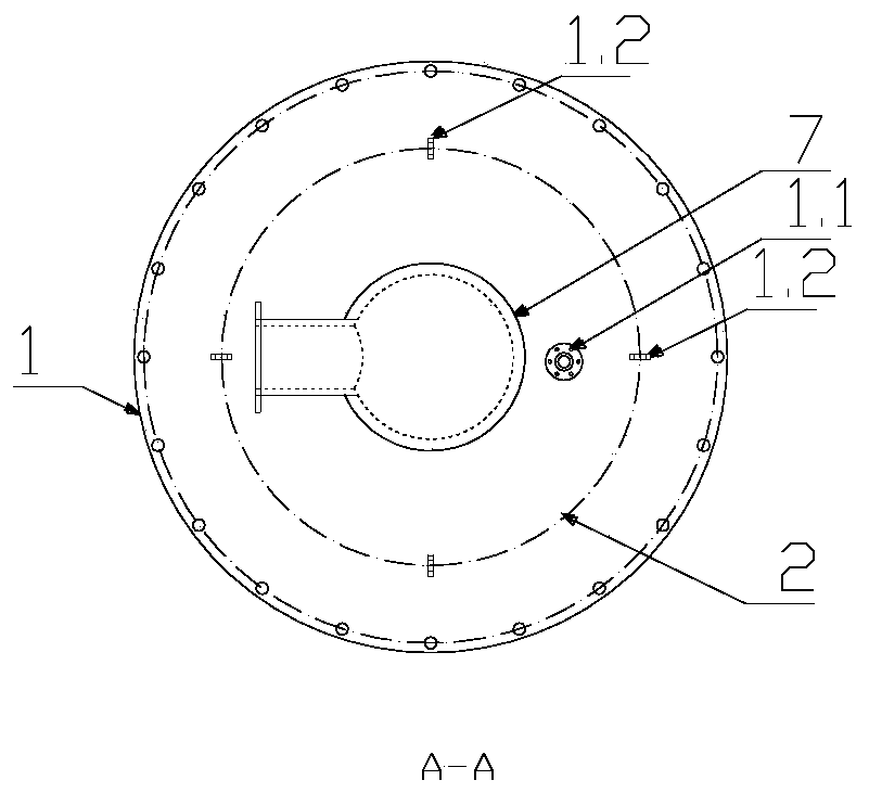
[0051] Such as Figure 1-12 The shown activated sludge cracking and separation integrated device includes an external shell barrel 1 and an internal rectifying barrel 2, and three spiral deflectors 3 are arranged symmetrically from top to bottom between the shell barrel 1 and the rectifying barrel 2; The bellows 4 is connected to the lower cover of the shell barrel 1, the hopper 5 is connected to the lower part of the bellows 4, and two vibrator brackets 5.1 are symmetrically arranged on the outer wall of the hopper 5;

[0052] A discharge pipe 6 is connected below the hopper 5; a discharge valve 6.1 is arranged on the discharge pipe 6; an inverted L-shaped exhaust pipe 7 is arranged in the center of the top cover of the shell barrel 1, and four symmetrically arranged on the upper cover...


PUM


Abstract

The invention discloses an activated sludge cracking and separating integrated device and process. The device comprises an outer shell barrel and an inner rectifying barrel; spiral guide plates are symmetrically arranged between the shell barrel and the rectifying barrel from top to bottom; a lower cover plate of the shell barrel is connected with a corrugated pipe, a hopper is connected to the lower portion of the corrugated pipe, and a discharging pipe is connected to the lower portion of the hopper; an inverted-L-shaped exhaust pipe is arranged in the center of a top cover of the shell barrel, and exhaust holes are symmetrically formed in the middle wall of the rectifying barrel in the circumferential direction; a sensor mounting flange is arranged on an upper cover plate of the shell barrel; a pressure and temperature instrument is mounted on the sensor mounting flange; a circular-truncated-cone-shaped inner flow guide piece is arranged at the bottom of the rectifying barrel. The device has the advantages of cyclone air separation, fluidized bed, plasma treatment and the like. Chemical reaction, material exchange and energy transfer processes exist, the whole process is carriedout in a high-pressure-difference high-speed environment, and the reaction rate is high.

Description

technical field [0001] The invention relates to a sludge treatment process, in particular to an activated sludge cracking and separation integrated device and its process. Background technique [0002] The disposal of excess sludge in sewage treatment plants has always been an environmental protection problem that plagues the stable operation of various sewage treatment plants. Normally, after the activated sludge has passed the identification of harmful substances, physical landfill is the first choice. With the development of urbanization, landfill plants are generally saturated, resulting in higher and higher landfill requirements and restrictions on sludge landfill. ; Simple high-temperature incineration is not economical, and there is also a risk of secondary pollution of dioxins. High-temperature combined incineration requires a coordinated unit, and the cost of harmless treatment is also high, and it is difficult to promote it; The principle of heat exchange takes up...

Claims


Application Information

Patent Timeline
Patent Type & Authority Applications(China)
IPC IPC(8): C02F11/10C02F11/00
CPCC02F11/006C02F11/008C02F11/10Y02W10/40
Inventor 白春李振王阳刘运东姚同祥陈宏
Owner 葛洲坝水务淄博博山有限公司
Why Eureka
Try Eureka