Prefabricated rail top air duct of subway station and hoisting installation method thereof

A technology for subway stations and track top air ducts, which is applied in pipeline layout, water conservancy projects, artificial islands, etc. It can solve the problems of long construction period, large consumption of material resources and energy, and uneconomical problems, and achieve the effect of reducing construction procedures

Pending Publication Date: 2020-04-10
CHINA RAILWAY 23RD CONSTR BUREAU LTD
View PDF1 Cites 4 Cited by
  • Summary
  • Abstract
  • Description
  • Claims
  • Application Information

AI Technical Summary

Problems solved by technology

However, the construction method of the cast-in-place method of the rail top air duct inside the subway station will bring some problems, mainly as follows: First, it needs to invest more manpower and material resources in the construction site for construction, there are many construction procedures, and all structural components are It needs to be completed at the construction site, and it needs to wait for the age of the concrete. This production method has a low degree of industrialization, low construction efficiency, and a long construction period; , large resource and energy consumption, large amount of construction waste, poor construction environment, heavy dust pollution on site, cross-operation with section construction, mutual constraints on construction period, etc.; cannot meet high quality, high efficiency, energy saving, and environmental protection. Sustainable development and construction requirements; Third, due to the particularity of the structure and location of the rail top air duct, the construction space is narrow, concrete vibration and surface smoothing are difficult, and the construction quality is not easy to guarantee; Fourth, the rail top air duct inside the subway station adopts existing The pouring method means that the civil construction needs to enter the site twice, which often takes up the later mechanical and electrical installation and decoration time, which directly affects the opening period of the whole line
[0004] Although the Chinese invention patent (publication number CN 110206274 A) solves the problems caused by the aforementioned cast-in-place construction method, however, in this Chinese invention patent, the embedded steel sleeve 9 of the middle plate penetrates the middle plate 23 of the platform layer in the vertical direction. , the water in the middle plate 23 of the platform layer will leak from the middle plate 23 of the platform layer to the air duct of the prefabricated assembled rail roof through the inner hole of the embedded steel sleeve 9 of the middle plate, thus affecting the normal use of the screen door of the subway station
In addition, in order to ensure the strength and pre-embed the pre-embedded connecting screw 11 on No. I prefabricated hanging wall 2 and No. II prefabricated hanging wall 3, the upper part of No. I prefabricated hanging wall 2 and No. II prefabricated hanging wall 3 needs to be thickened And the lower part of No. Ⅰ prefabricated hanging wall 2 and No. Ⅱ prefabricated hanging wall 3 is roughly plate-shaped (except the hanging wall ear plate 13), and the lower part is provided with hanging wall ear plate 13, and the prefabricated air duct plate 4 is arranged on the hanging wall ear Plate 13, in order to bear the weight of the prefabricated air duct slab 4, the lower part of No. 1 prefabricated hanging wall 2 and No. 2 prefabricated hanging wall 3 must also ensure the necessary thickness in order to ensure the strength, so that No. The overall weight of the wall 3 is relatively heavy, and it is inconvenient to hoist. After being hoisted on the middle plate 23 of the platform layer, the pre-embedded connecting screw 11 of the hanging wall and the fastening nut 10 of the middle plate screwed together with it need to bear a relatively large load, which affects the service life. Also uneconomical
[0005] How to solve the problem that water enters the prefabricated rail top air duct through the station middle plate and the prefabricated prefabricated rail top air duct is affected by the heavy weight of components such as No. become an urgent technical problem to be solved

Method used


Image

  • Prefabricated rail top air duct of subway station and hoisting installation method thereof
  • Prefabricated rail top air duct of subway station and hoisting installation method thereof
  • Prefabricated rail top air duct of subway station and hoisting installation method thereof

Examples


Embodiment Construction

[0051] The examples given below are specific descriptions of the present invention, and it is necessary to point out that the following examples are only used to further illustrate the present invention, and cannot be interpreted as limiting the protection scope of the present invention.

[0052] In the present invention, descriptions involving "first", "second", "third", "fourth", "fifth", "sixth", "seventh", "eighth" and so on are only used for Descriptive purposes, and should not be understood as indicating or implying their relative importance or implying the number of technical features indicated. Thus, the features defined as "first", "second", "third", "fourth", "fifth", "sixth", "seventh" and "eighth" may be expressed or implied Inclusively including at least one of these features.

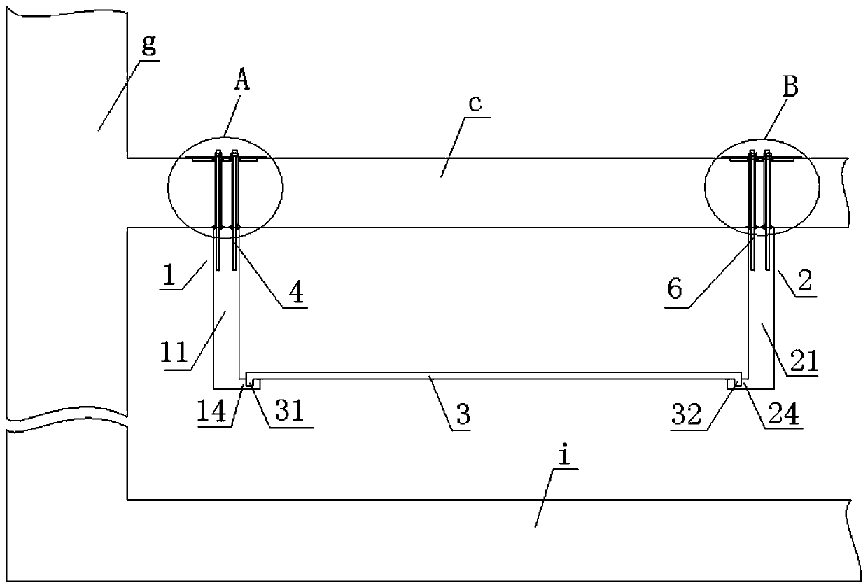
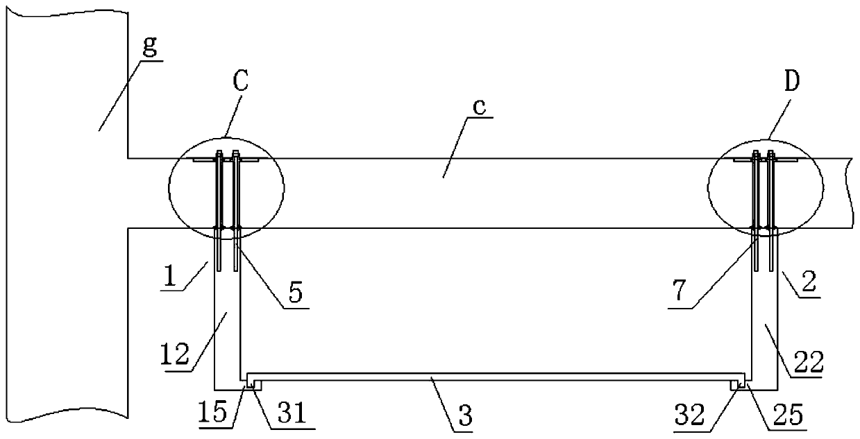
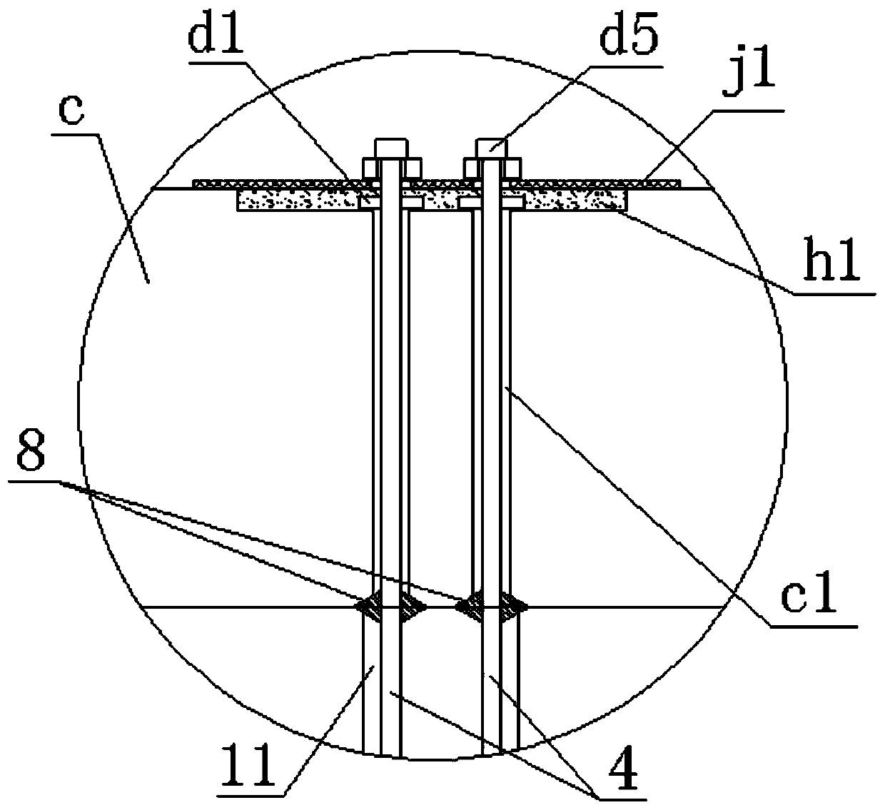
[0053] Figure 1-6 An embodiment of a prefabricated rail top air duct of a subway station among numerous embodiments of the present invention is shown as an example, figure 1 , 2 Among...


PUM


Abstract

The invention discloses a prefabricated rail top air duct of a subway station. The prefabricated rail top air duct of the subway station comprises a first prefabricated side plate, a second prefabricated side plate, an air duct bottom plate, a first screw rod, a second screw rod, a third screw rod, a fourth screw rod, a first waterproof rubber ring, a second waterproof rubber ring, a third waterproof rubber ring and a fourth waterproof rubber ring, wherein the first prefabricated side plate comprises a first upright post, a second upright post, a first panel, a first side foot plate and a second side foot plate; the second prefabricated side plate comprises a third upright post, a fourth upright post, a second panel, a third side foot plate and a fourth side foot plate; and the air duct bottom plate is lapped on the first side foot plate, the second side foot plate, the third side foot plate and the fourth side foot plate. The invention also discloses a hoisting installation method ofthe prefabricated rail top air duct of the subway station. According to the prefabricated rail top air duct of the subway station and the hoisting installation method thereof, the construction periodcan be shortened, the construction quality can be improved, the construction cost can be reduced, the safe and civilized construction degree can be improved, the water can be prevented from leaking from a middle plate of the station to a rail top air duct, the normal use of a shielding door of the subway station can be ensured, and the problem that the service life of the prefabricated rail top air duct is influenced due to heavy weight of components can be solved.

Description

technical field [0001] The invention relates to a rail top air duct of a subway station and its construction technology, in particular to a prefabricated rail top air duct of a subway station and a hoisting and installation method thereof. Background technique [0002] The rail top air duct is the top exhaust air duct of the train, which is an important internal structural component in the ventilation system of the subway station. It is suspended at the junction of the station middle plate and the structural side wall. Due to the particularity of its location, it is generally not poured at the same time as the main body of the station, especially in stations where the shield tunnel construction needs to pass, the rail top air duct must be poured later. [0003] During the construction stage, subway stations are generally used as shield tunnels to start or arrive at the site. Therefore, the secondary structures such as rail top air ducts inside the station are usually complet...

Claims


Application Information

Patent Timeline
Patent Type & Authority Applications(China)
IPC IPC(8): E02D29/045F24F13/02
CPCE02D29/04F24F13/02
Inventor 张彪刘延龙奚成李大源林晓波黄山泉翟勇霍莉刘陈坤
Owner CHINA RAILWAY 23RD CONSTR BUREAU LTD
Why Eureka
Try Eureka