Polishing device for optical lens production

A technology for optical lenses and mounting blocks, which is applied in grinding drive devices, grinding/polishing safety devices, machine tools suitable for grinding workpiece edges, etc., can solve the problems of product scrap, inaccurate positioning, and low work efficiency, etc. Achieve the effect of fast work efficiency, reduce pollution and improve grinding quality

Pending Publication Date: 2020-04-14
江苏新事通光电科技有限公司
View PDF15 Cites 8 Cited by
  • Summary
  • Abstract
  • Description
  • Claims
  • Application Information

AI Technical Summary

Problems solved by technology

[0003] In the process of optical lens processing, in order to adapt to the installation structure, the rough edge of the lens needs to be edging. In the prior art, the optical lens needs to be manually placed on the fixture of the edging machine for edging. For processing, when the lens is installed on the fixture, it is necessary to ensure that the fixture is clamped at the center of the lens, so as to avoid the excessive grinding amount of the edge grinding and cause the product to be scrapped. Nowadays, the staff usually use their eyes to observe the clamping position, or simply measure, and the positioning is not correct. Accurate, low work efficiency, therefore, in view of the above status quo, there is an urgent need to develop a polishing device for optical lens production to overcome the shortcomings in current practical applications

Method used


Image

  • Polishing device for optical lens production
  • Polishing device for optical lens production
  • Polishing device for optical lens production

Examples


Embodiment 1

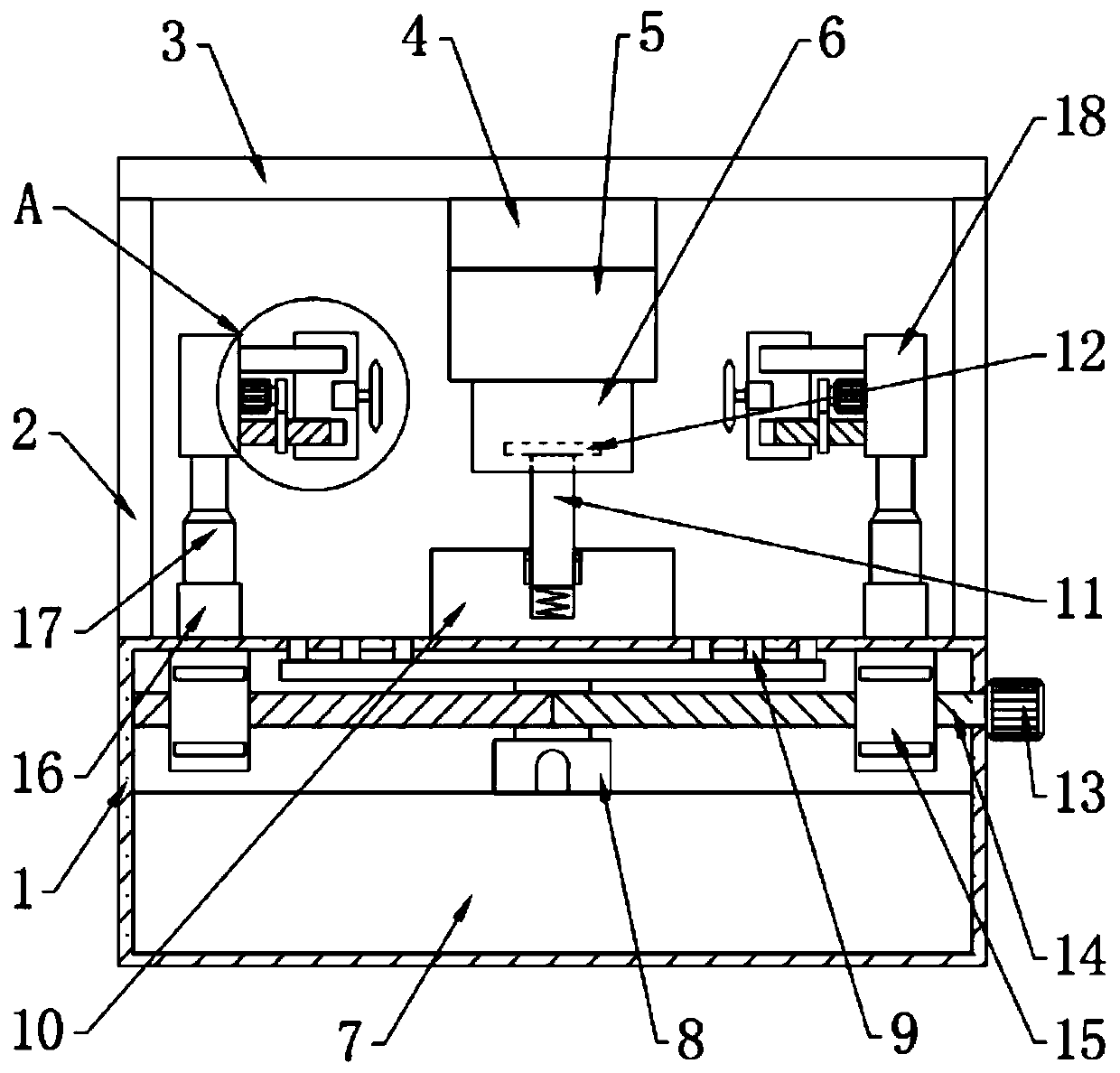
[0026] see Figure 1-5 , in an embodiment of the present invention, a polishing device for optical lens production includes a base 1, a fixing mechanism for fixing the optical lens is provided on the top of the base 1, and an edge grinding mechanism is provided on the left and right sides of the fixing mechanism. The inner side of the base 1 is provided with a dust removal mechanism.

Embodiment 2

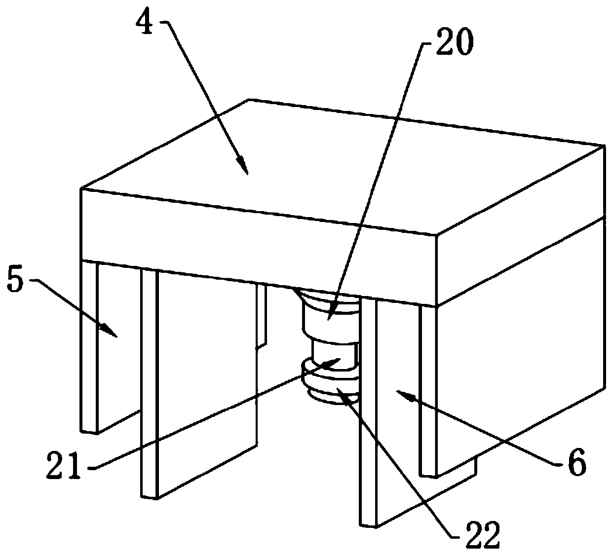
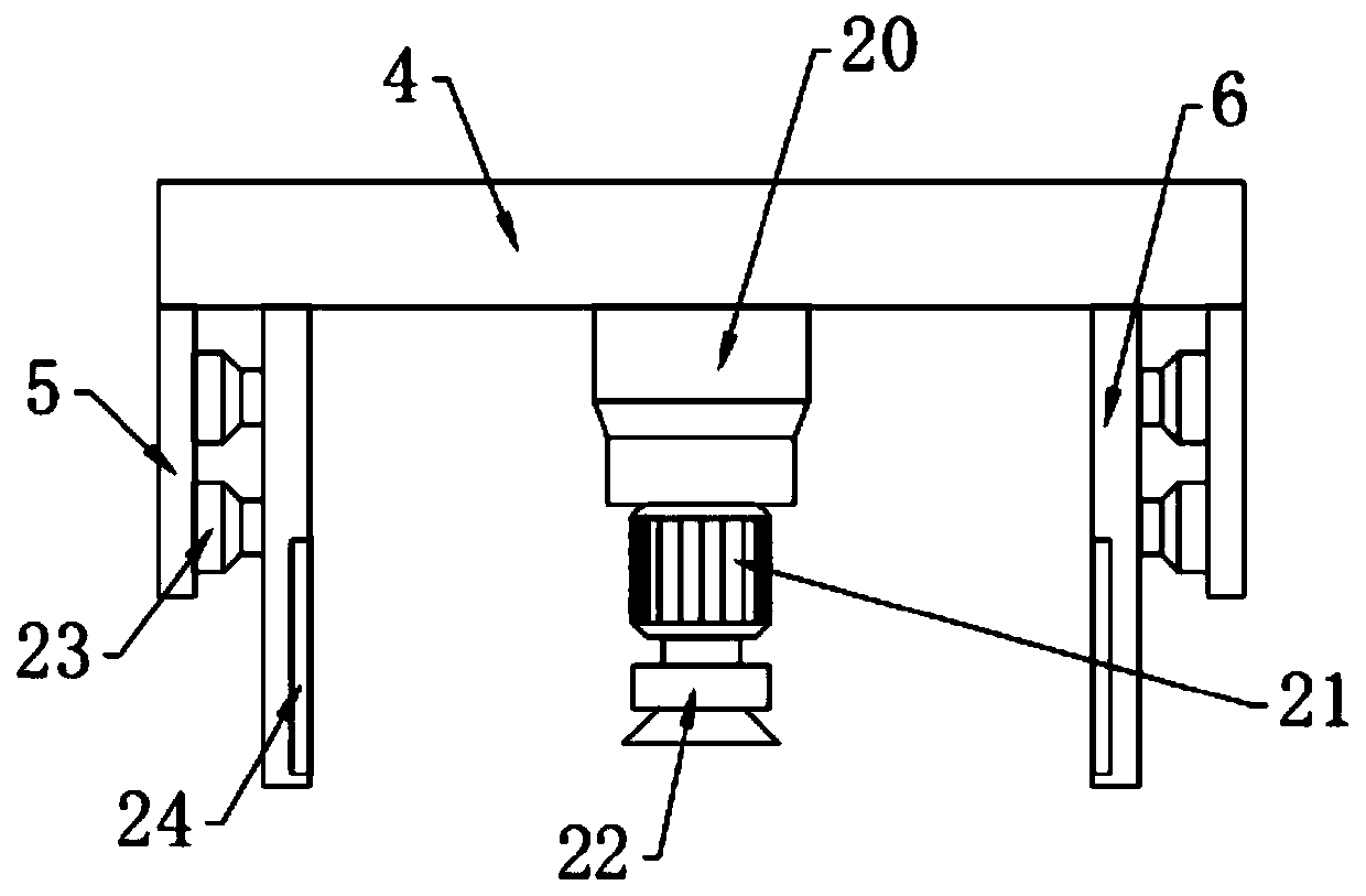
[0028] In this embodiment, the fixing mechanism includes support plates 2 arranged on the left and right sides of the base 1, the top of the support plate 2 is fixedly connected with a top plate 3, and the bottom of the center of the top plate 3 is fixedly connected with a fixed plate 4, The front and rear ends of the fixed plate 4 are all fixedly connected with a baffle plate 5, and the opposite side of the baffle plate 5 on both sides is provided with a splint 6 that is slidingly connected with the fixed plate 4. Between the splint 6 and the baffle plate 5 The third telescopic rod 23 is fixedly connected, and the second telescopic rod 20 fixedly connected with the fixed plate 4 is arranged between the splints 6 on both sides. The bottom of the second telescopic rod 20 is fixedly connected with a second motor 21, The output end of the second motor 21 is connected to the pressing block 22 , the bottom of the pressing block 22 is provided with a suction cup, and the lower side o...


PUM


Abstract

The invention relates to the technical field of optical lens production and especially relates to a polishing device for optical lens production. The device comprises a base. A fixing mechanism for fixing an optical lens is arranged at a top of the base. Edge grinding mechanisms are arranged on a left side and a right side of the fixing mechanism. A dedusting mechanism is arranged inside the base. In the invention, the fixing mechanism is arranged, movement of two side clamping plates is used, the lens positioned at a top end of a placing disc is always located in a center of the placing disc, and a pressing block is used for stably fixing the lens so that product scrap caused by clamping deviation of the lens to be processed is avoided, and positioning precision is high; positions of polishing wheels on two sides can be rapidly adjusted by arranging a first motor, and polishing precision is guaranteed by arranging a third motor and finely adjusting the positions of the polishing wheels; and polishing quality can be improved, and pollution to the environment can be reduced by arranging the dedusting mechanism.

Description

technical field [0001] The invention relates to the technical field of optical lens production, in particular to a polishing device for optical lens production. Background technique [0002] Optical glass is mixed with oxides of high-purity silicon, boron, sodium, potassium, zinc, lead, magnesium, calcium, barium, etc. according to a specific formula, melted at high temperature in a platinum crucible, stirred evenly with ultrasonic waves, and removed air bubbles, and then subjected to long-term Slowly cool down over time to avoid internal stress in the glass block. The cooled glass block has excellent properties such as transparency, uniformity, refractive index and dispersion rate, and has been widely used in the field of optical lens technology. Optical lenses are important components for imaging through the refraction of light, and are generally used in optical equipment such as cameras and microscope lenses. [0003] In the process of optical lens processing, in order t...

Claims


Application Information

Patent Timeline
Patent Type & Authority Applications(China)
IPC IPC(8): B24B9/14B24B41/06B24B49/00B24B47/12B24B55/06B24B47/22
CPCB24B9/14B24B9/146B24B41/06B24B47/12B24B47/22B24B49/00B24B55/06
Inventor 袁叶军
Owner 江苏新事通光电科技有限公司
Why Eureka
Try Eureka