

Method and device for measuring thickness of hearth wall of blast furnace online
A blast furnace and furnace wall technology, which is applied in the field of blast furnace wall thickness measurement, can solve the problems such as the inability to effectively measure the thickness of the hearth furnace wall, the inability to realize continuous monitoring of the thickness of the hearth furnace wall, and the limitation of the thickness of the hearth furnace wall, etc. Achieve the effect of being conducive to safe and stable operation, avoiding monitoring blind spots, and reducing erosion rate
- Summary
- Abstract
- Description
- Claims
- Application Information
AI Technical Summary
Problems solved by technology
Method used
Image

Examples
Embodiment 1
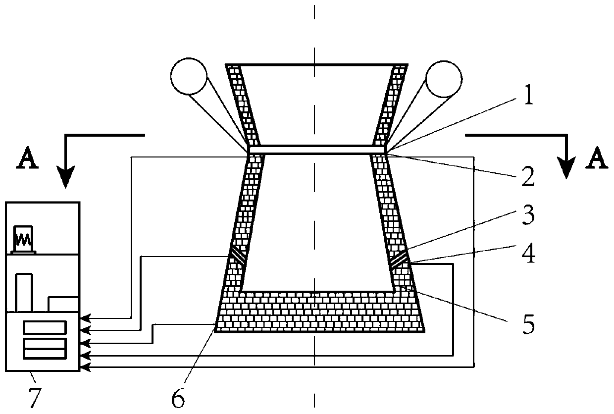
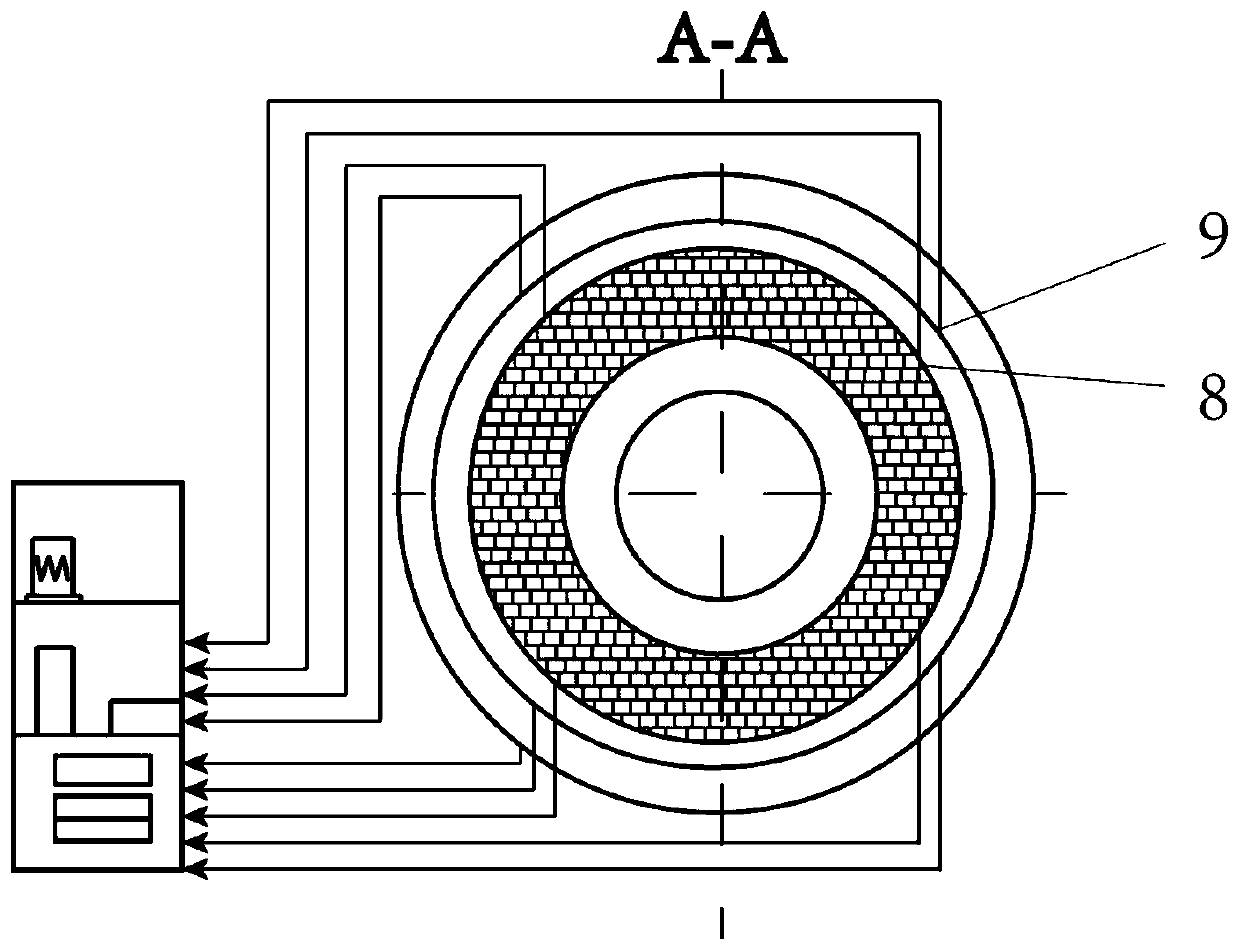
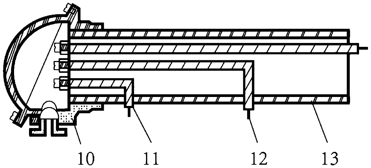
[0035] In this example, see Figure 1-Figure 4 , a method for online measurement of the thickness of a hearth wall of a blast furnace, comprising the steps of:
[0036] a. Set a series of electromotive force measurement points at the positions of the blast furnace hearth hearth wall where the horizontal plane height position of the center of the tuyere and the center of the tap hole are set, and each electromotive force measurement point is located at a different height level, and The electromotive force measurement points are respectively located on the refractories and the furnace shell at different depths of the furnace wall, so that the electromotive force measurement points on the same layer at the same height are installed symmetrically and evenly along the horizontal circumference of the hearth, and the blast furnace hearth The electromotive force measurement points at the same azimuth position of the wall are distributed at equal intervals on the refractory materials a...
Embodiment 2
[0050] This embodiment is basically the same as Embodiment 1, especially in that:
[0051] In this embodiment, when using the method of online measurement of the wall thickness of the blast furnace hearth, the measured value of the electromotive force signal collected in step a and the reference value of the electromotive force signal collected in step b are compared and analyzed and processed to obtain real-time Measured blast furnace hearth wall thickness information and slag-iron liquid level information. In this embodiment, while measuring the thickness information of the blast furnace hearth wall in real time, it can also measure the slag-iron liquid level information, including the height change information of the slag-iron interface. Due to the difference in the physical properties of the material, the energy of the slag and molten iron in the hearth passes through the ceramic cup, carbon brick, ramming material and furnace shell, and there is a certain difference in th...
PUM
 Abstract
Description
Claims
Application Information