Normal-pressure single-effect evaporator of heat pump and use method of evaporator

A single-effect evaporation and normal pressure technology, which is applied in the direction of evaporator/condenser, heat pump, lighting and heating equipment, etc., can solve the problems of difficult detection, high system cost, damage to the vacuum degree of the system, etc., achieve stable operation and reduce cost cost, the effect of increasing cost

Active Publication Date: 2020-04-17
苏州荣轩环保有限公司
View PDF6 Cites 1 Cited by
  • Summary
  • Abstract
  • Description
  • Claims
  • Application Information

AI Technical Summary

Problems solved by technology

[0004] The present invention provides a heat pump atmospheric pressure single-effect evaporator and its use method, which can effectively solve the problem that the existing heat pump single-effect evaporator has high requirements on the airtightness of the system in the above-mentioned background technology. If a certain interface in the system Air leakage will destroy the vacuum degree of the system, thereby destroying the evaporation process, and it is difficult to detect air leakage in a certain place during actual use, and can only be checked at one place; When performing maintenance such as checking, replacing or cleaning sensors, the machine must be shut down; when the evaporator is performing slag discharge or material discharge, the slag or material discharge can only be performed by temporarily reducing the vacuum degree of the system or shutting down; due to the high vacuum degree of the system High, so all accessories need to be configured according to the higher vacuum degree, which makes the system cost higher; in the case of high anti-corrosion requirements, only corrosion-resistant metals such as titanium can be used, and the system cost is higher.

Method used


Image

  • Normal-pressure single-effect evaporator of heat pump and use method of evaporator
  • Normal-pressure single-effect evaporator of heat pump and use method of evaporator

Examples


Embodiment

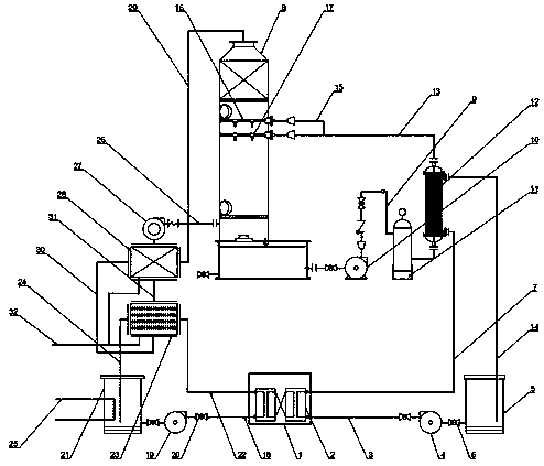
[0033] Example: such as Figure 1-2As shown, the present invention provides a technical solution, a heat pump atmospheric pressure single-effect evaporator, including a heat pump unit 1, the selection of the heat pump unit 1 is M-08, the heat pump unit 1 includes a refrigerant compressor and an evaporator, and the refrigerant compression The evaporator is mainly used to compress the refrigerant, and the evaporator is mainly used to reduce the pressure of the refrigerant to achieve refrigeration, which is convenient for the refrigerant to be compressed and depressurized for refrigeration. The heat pump unit 1 is equipped with a coil heat exchanger 2 inside, and the bottom position of the heat pump unit 1 is The hot water supply pipe 3 is connected to the hot water supply pipe 3, and the end of the hot water supply pipe 3 far away from the heat pump unit 1 is connected to the hot water buffer tank 5. The selected model is P701, hot water pipe valve 6 is installed on both sides o...


PUM


Abstract

The invention discloses a normal-pressure single-effect evaporator of a heat pump and a use method of the evaporator. The bottom of one side of a heat pump unit is connected with a hot water supply pipe. The end, away from the heat pump unit, of the hot water supply pipe is connected with a hot water buffering tank. The top of one side of the heat pump unit is connected with a hot water inlet pipe. Through the heat pump unit, a coiled pipe heat exchanger, the hot water supply pipe, a hot water circulating pump, the hot water buffering tank, a hot water pipe valve, the hot water inlet pipe, a cold water supply pipe, a cold water circulating pump, a cold water pipe valve, a cold water buffering tank and a cooling water inlet pipe, hot water and cold water can be generated for heating an evaporated raw material and condensing exhausted gas, so the system is a low-temperature evaporator at a normal-pressure state, no pressurizing or vacuumizing is involved, and the operation of the systemis more stable; and meanwhile, since the interior of the whole system is at a normal-pressure state, emptying and deslagging can be performed on an evaporation tower at any time by people, and nozzlesin the evaporation tower can be cleaned or replaced at any time.

Description

technical field [0001] The invention relates to the technical field of heat pump evaporators, in particular to a heat pump atmospheric pressure single-effect evaporator and a method for using the same. Background technique [0002] The heat pump evaporator is a new type of evaporator, also known as a thermal compression evaporator. The evaporation method is to compress the secondary steam from the evaporator to a higher pressure by a compressor or a turbine, and then recycle it to make up The heat of evaporation is used to reduce the consumption of steam. The existing heat pump single-effect evaporator uses the principle of vacuuming to reduce the boiling point of water, and the boiling point of water is lowered by 35-55°C, so that the heat pump can be used to heat the water. The temperature is raised to 35-55°C to realize the process of evaporation; [0003] In the actual use process, the existing heat pump single-effect evaporator has the following hidden dangers in the p...

Claims


Application Information

Patent Timeline
Patent Type & Authority Applications(China)
IPC IPC(8): F25B39/02F25B30/00
CPCF25B30/00F25B39/02
Inventor 武善国
Owner 苏州荣轩环保有限公司
Why Eureka
Try Eureka