Finite element analysis method of piston

An analysis method and finite element technology, applied in the field of computer-aided engineering of mechanical structures, can solve problems such as the inability to accurately reflect the stress, strain and fatigue of the piston, and the distribution and deformation of the piston stress.

Active Publication Date: 2020-04-17
BINZHOU BOHAI PISTON CO LTD
View PDF3 Cites 2 Cited by
  • Summary
  • Abstract
  • Description
  • Claims
  • Application Information

AI Technical Summary

Problems solved by technology

[0005] The actual production process of the piston inlaid with alumina ceramic fiber composite material at the throat is to make a uniform and porous ceramic fiber preform, and then the matrix alloy aluminum liquid is filled into the pores of the ceramic preform by pressure infiltration to form a composite material, the aluminum matrix and There is a transition area on the joint surface of the composite material, and there will not be a large residual stress, and after the piston is heat-treated, the residual stress near the joint surface will be reduced a lot, but for the finite element analysis of the composite material piston, the composite in the model The material part and the aluminum matrix are made separately, and the transition area cannot be reflected. Due to the differences in material properties such as thermal conductivity, density, and elastic modulus of the alumina ceramic fiber composite material and the aluminum alloy matrix material, when mechanical loads are applied to the piston After the temperature load, the piston deforms and generates stress, but the residual stress will be generated on the joint surface of the two materials due to the difference in material properties, and the existence of residual stress will affect the distribution of the overall stress of the piston, resulting in that the analysis results cannot accurately reflect the The stress, strain and fatigue of the piston, how to eliminate the residual stress at the joint surface and its vicinity or avoid the influence of the residual stress on the analysis results has become a big problem in the finite element analysis

Method used


Image

  • Finite element analysis method of piston
  • Finite element analysis method of piston
  • Finite element analysis method of piston

Examples


Embodiment Construction

[0031] In order to enable those skilled in the art to better understand the present invention, the following will be combined with the attached Figure 1-4 The technical scheme of the present invention is further described.

[0032] refer to Figure 1 to Figure 4 Shown, the present invention is a kind of finite element analysis method of piston and comprises the following steps:

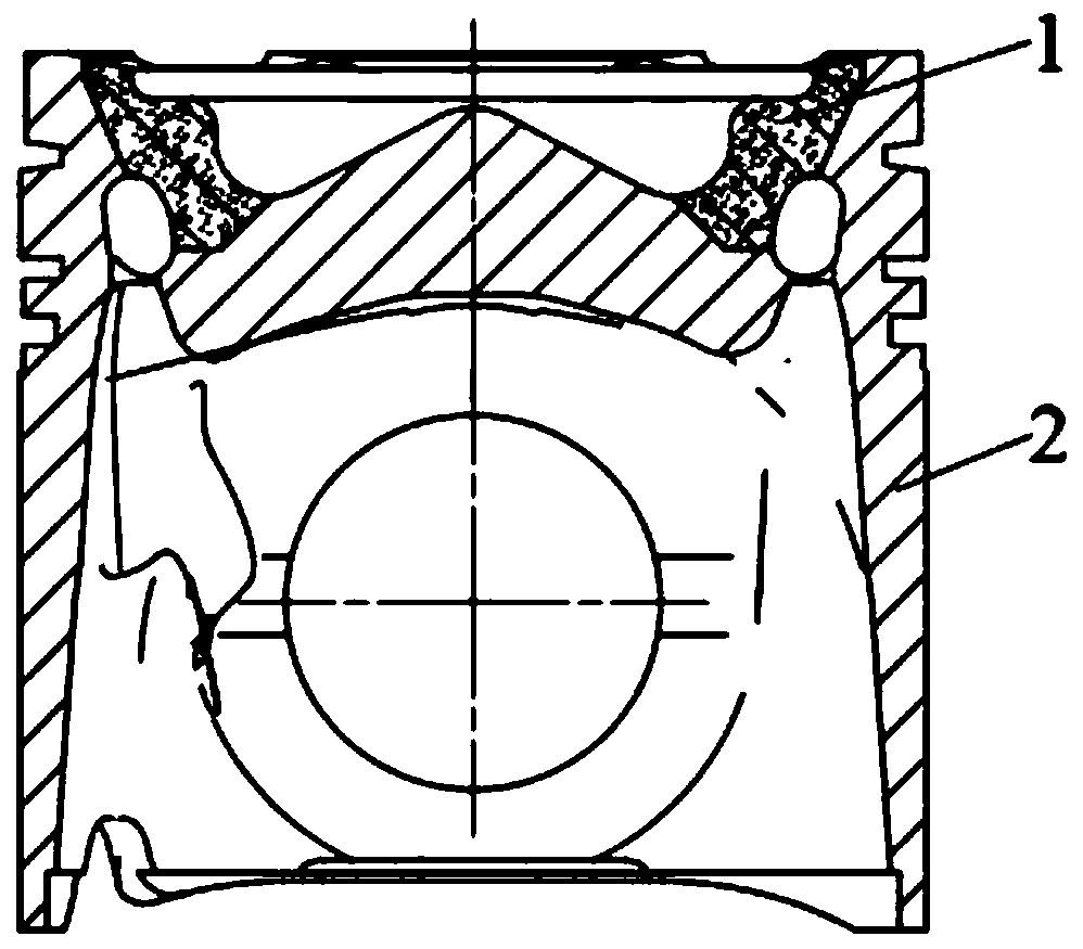
[0033] Step 1, using 3D modeling software to establish a geometric model of the piston 3 including the aluminum alloy matrix 2 and the alumina ceramic fiber composite material part 1 . Commonly used three-dimensional modeling software includes UG, Solid Works, pro-e etc., draws three-dimensional model with UG in the present embodiment, as figure 1 shown;

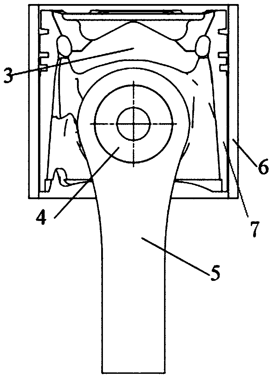
[0034] Step 2, on the basis of step 1, establish a model of components related to the piston 3 including the piston pin 4, the connecting rod 5 and the sleeve cylinder 6. Due to the complex structure of the piston, it is usually necessary to si...


PUM


Abstract

The invention relates to a finite element analysis method of a piston. The method comprises the following steps: establishing a geometric model of the piston comprising an aluminum alloy matrix and analuminum oxide ceramic fiber composite material part; establishing a model of a piston-related component comprising a piston pin, a connecting rod and a sleeve cylinder; importing the geometric modelof the piston and related components into CAE analysis software, partially bonding the aluminum alloy matrix to the aluminum oxide ceramic fiber composite material together by using a bonding command, and defining the material attributes of the aluminum alloy matrix and the aluminum oxide ceramic fiber composite material as aluminum alloy or aluminum oxide ceramic fiber composite material to obtain a model 1 or a model 2; dividing grids; applying constraints; simulating actual working conditions to perform temperature and mechanical loading, and calculating stress and strain analysis resultsof the model 1 or the model 2; and importing the calculation result in the step 6 into fatigue analysis software to obtain a fatigue calculation result of the model 1 or the model 2. Unified materialattributes are adopted, residual stress caused by poor material performance is effectively avoided, and an analysis result is more accurate.

Description

[0001] (1) Technical field [0002] The invention relates to the technical field of computer-aided (CAE) engineering of mechanical structures, in particular to a finite element analysis method of a piston. [0003] (2) Background technology [0004] In recent years, with the development trend of high efficiency, low fuel consumption and low emission, engine power and explosion pressure have also increased, and the thermal load and mechanical load on the piston have become higher and higher. The highest place, usually the throat is the part with the highest temperature in the combustion chamber. When the piston is operating under high load, the throat temperature may even exceed the fatigue limit of the piston material, resulting in fatigue cracking or failure due to excessive thermal stress. Therefore, for high-load engines, a piston with a throat inlaid with alumina ceramic fiber composite material has been developed to increase the strength of the throat and improve its abili...

Claims


Application Information

Patent Timeline
Patent Type & Authority Applications(China)
IPC IPC(8): G06F30/23
CPCY02T90/00
Inventor 刘世英张俊青李猛猛吴义民赵旭东贾艳熊培友郭庆元
Owner BINZHOU BOHAI PISTON CO LTD
Why Eureka
Try Eureka