
Plasma surface modification device for improving carbon deposition resistance of spark plug

A plasma and surface modification technology, which is applied in the field of spark plugs, can solve problems such as inability to uniformly treat the surface, achieve the effects of improving surface electrical properties, optimizing ignition and fuel injection control strategies, and solving the effect of surface carbon

Active Publication Date: 2020-04-17
NANJING UNIV OF TECH
View PDF17 Cites 0 Cited by
  • Summary
  • Abstract
  • Description
  • Claims
  • Application Information

AI Technical Summary

Problems solved by technology

However, since the surface of the insulating ceramic of the spark plug has a truncated-like structure, the above two patents cannot uniformly treat the entire surface

Method used


Image

  • Plasma surface modification device for improving carbon deposition resistance of spark plug
  • Plasma surface modification device for improving carbon deposition resistance of spark plug
  • Plasma surface modification device for improving carbon deposition resistance of spark plug

Examples


Embodiment 1

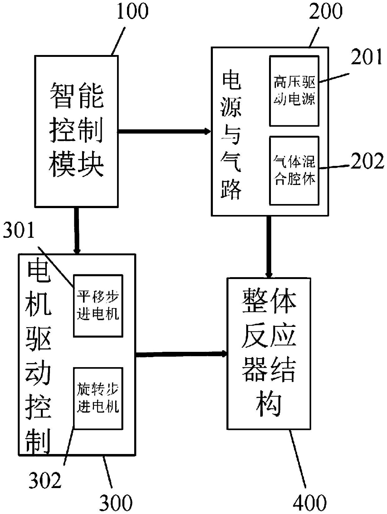
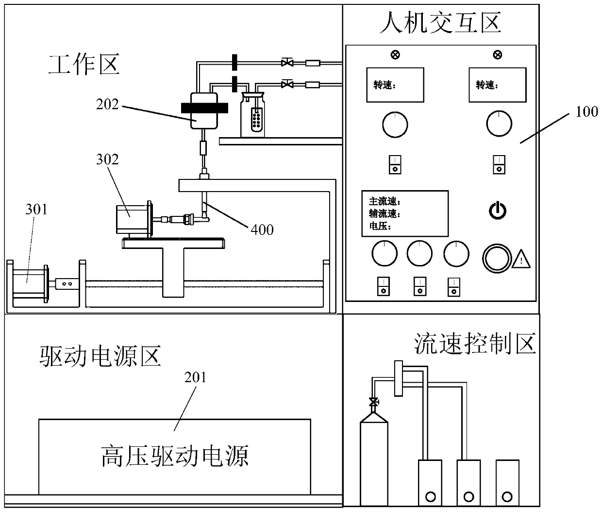
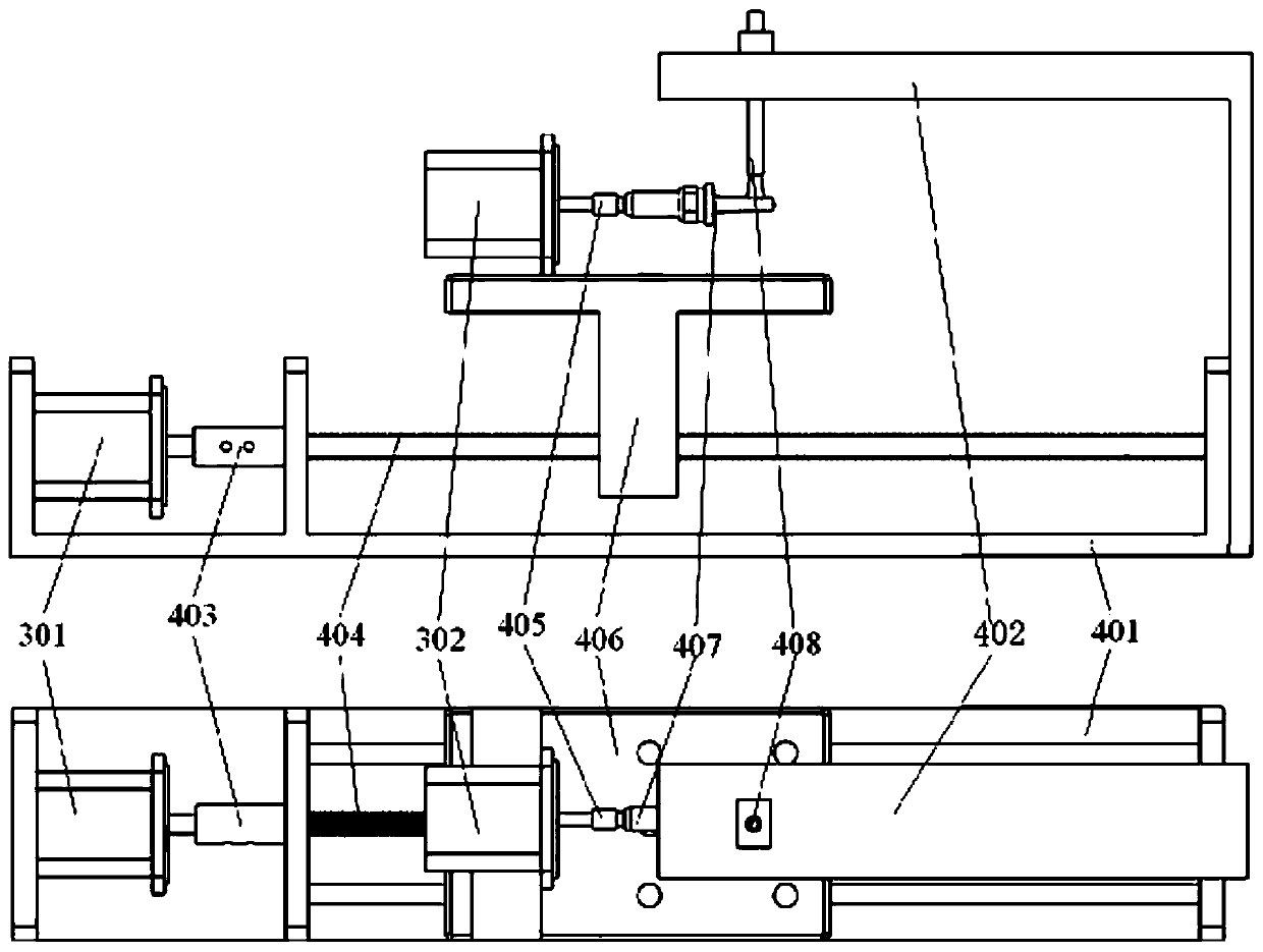
[0037] The invention provides a plasma surface modification device for improving the anti-carbon deposition ability of the spark plug. The device uses active particles generated by jet discharge to treat the surface of the insulating ceramic of the spark plug to change its surface microscopic morphology and chemical composition, thereby achieving two aspects. Effect: On the one hand, it reduces the polarity of the surface to inhibit the formation of carbon deposits; on the other hand, it improves the electrical properties of the surface, reduces the surface resistance, and increases the withstand voltage along the surface. The following will combine image 3 Describe the overall device structure and its operating principle.

[0038] image 3 A schematic diagram of the overall reactor structure.

[0039] The overall reactor structure 400 includes a stainless steel support base 401, a jet tube clamp 402, a translation screw coupling 403, a translation screw 404, a spark plug c...

Embodiment 2

[0048] The above-mentioned overall plasma coating process will be introduced below, and the specific workflow is as follows: Image 6 shown. First open the gas cylinder, turn on the main flow rate valve-controlled switch 115 and the auxiliary flow rate valve-controlled switch, usually we choose Ar gas as the working gas, add a precursor in the gas washing bottle 2026, usually select a silicon-containing organic liquid compound (such as Hexa base disiloxane HMDSO). When adjusting the flow rate, the adjustment range of the flow rate of the main air path is 0-5L / min, generally controlled at 1L / min, the adjustment range of the flow rate of the auxiliary air path is 0-100mL / min, generally controlled at 20mL / min, the flow rate can be adjusted according to the modification effect Appropriate adjustments. The power supply is pulse-driven power supply, the fixed pulse frequency is 5kHz, the pulse rising and falling edges are 100ns, the pulse width is 800ns, the adjustment amplitude r...


PUM


Abstract

The invention discloses a plasma surface modification device for improving the carbon deposition resistance of a spark plug in the field of spark plugs. The plasma surface modification device comprises an intelligent control module, a power supply and gas circuit, a motor drive controller and an integral reactor structure, the power supply and gas circuit comprises a high-voltage driving power supply and a gas mixing cavity; and the motor drive control comprises a translation stepping motor and a rotation stepping motor. The high-voltage driving power supply is connected to the power supply wiring end of the whole reactor structure, the hydrophobic plasma jet is used for changing the microscopic porous structure and reducing the surface energy, the automatic displacement platform is matched to achieve uniform treatment, and finally the carbon deposition resistance and ignition performance of the spark plug are improved.

Description

technical field [0001] The invention relates to the technical field of spark plugs, in particular to a plasma surface modification device for improving the carbon deposition resistance of spark plugs. Background technique [0002] The spark plug is the core component of the ignition system of a fuel vehicle. It uses the electric spark generated by high-voltage breakdown to ignite the mixed oil and gas in the cylinder, and then promotes the displacement of the piston and the operation of the engine. The quality of its ignition performance will directly affect the output power of the engine. So the spark plug is also known as the "heart" of the gasoline engine. Maintaining the high-efficiency ignition performance of spark plugs can not only obtain a comfortable and stable driving experience, but also help to extend the working life of the engine and transmission. [0003] The spark plug belongs to the easy-to-failure part of the car. The reason is that the carbon on the surfa...

Claims


Application Information

Patent Timeline
Patent Type & Authority Applications(China)
IPC IPC(8): H01T21/02H01B19/04H05H1/24
CPCH01T21/02H01B19/04H05H1/2406
Inventor 崔行磊方志严冰梅丹华
Owner NANJING UNIV OF TECH
Learn More