
Mixer and high-temperature flue gas treatment device with same

A processing device and mixer technology, applied in gas treatment, fluid mixer, mixer, etc., can solve the problems of low ozone, secondary pollution, environmental pollution, etc., to increase contact time, accelerate mixing, increase contact area effect

Inactive Publication Date: 2020-04-21
安徽微宇仪器科技有限公司
View PDF8 Cites 0 Cited by
  • Summary
  • Abstract
  • Description
  • Claims
  • Application Information

AI Technical Summary

Problems solved by technology

[0002] Magnesia-carbon bricks need to be added with phenolic resin as a binder during the production process, and during the drying process of magnesia-carbon bricks, some formaldehyde and phenol gases will volatilize into the air when the phenolic resin solidifies, and then discharge them outside the furnace, polluting the environment
At present, the ozone ions produced by ultraviolet radiation are generally used to oxidize phenol and formaldehyde, but the amount of ozone produced by UV photolysis is very small, and the flue gas needs to be cooled during the UV photolysis process. The temperature of the flue gas generated is about 80°C, while the allowable range of the UV photolysis working temperature is below 40°C, and the flue gas discharge per hour needs a large amount of cooling water when the flue gas discharge is nearly 10,000 cubic meters. When the flue gas contacts with water, a large amount of harmful gas Dissolved in water, if it is discharged, it will cause secondary pollution, if it is disposed of, it will increase a lot of production costs and cause unnecessary waste

Method used


Image

  • Mixer and high-temperature flue gas treatment device with same
  • Mixer and high-temperature flue gas treatment device with same

Examples


Embodiment Construction

[0018] Embodiments of the present invention are described in detail below, examples of which are shown in the drawings, wherein the same or similar reference numerals denote the same or similar elements or elements having the same or similar functions throughout. The embodiments described below by referring to the figures are exemplary only for explaining the present invention and should not be construed as limiting the present invention.

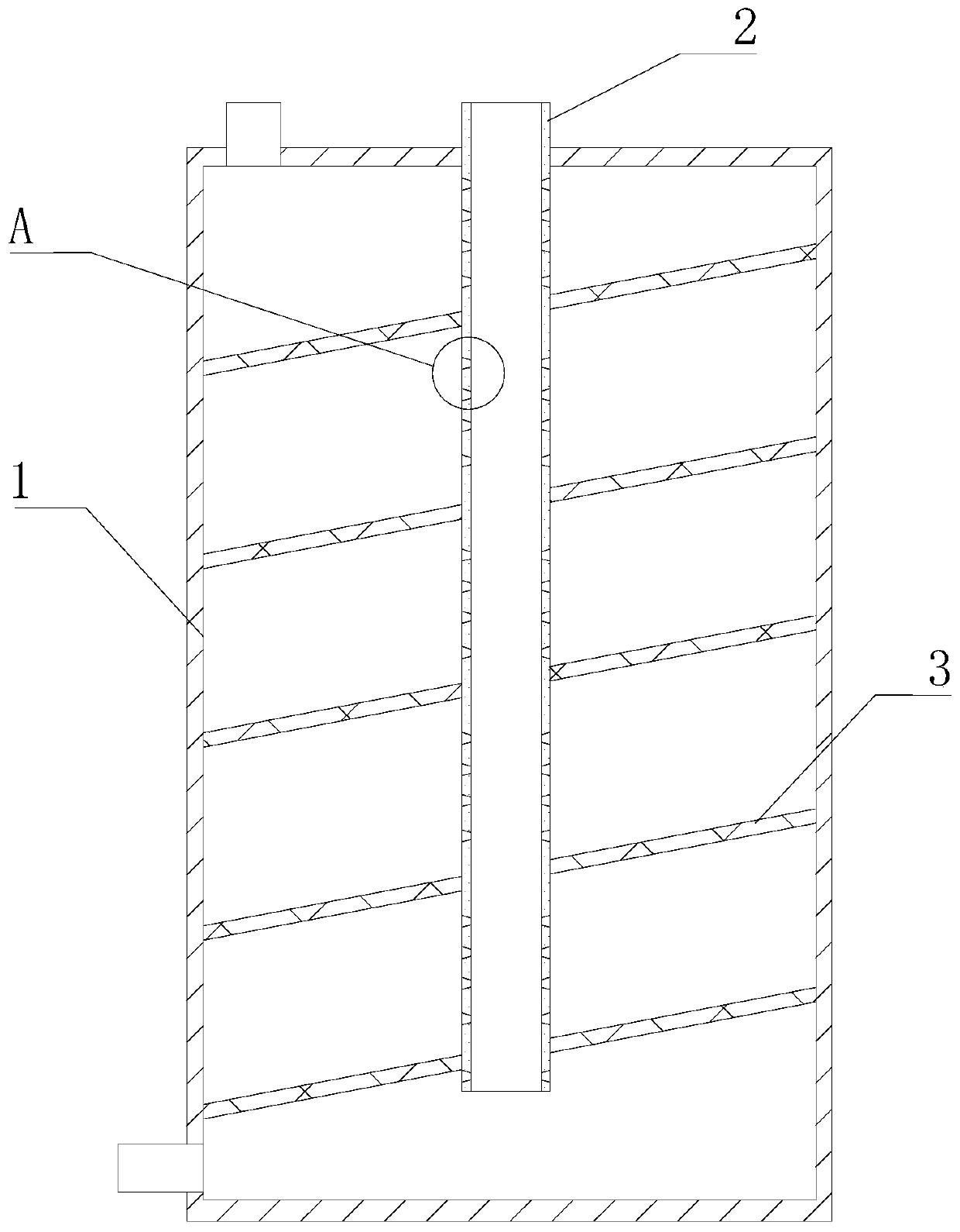
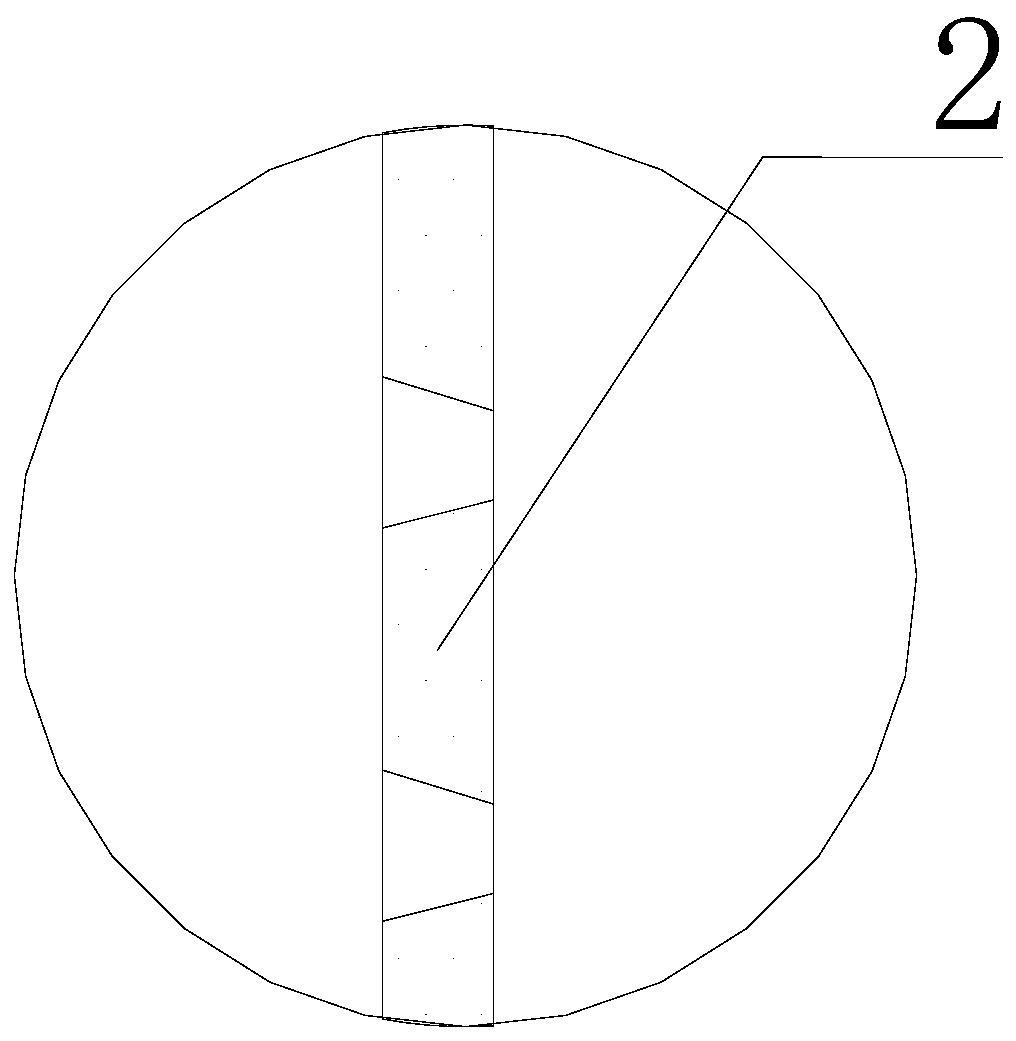
[0019] refer to figure 1 and figure 2 , a kind of mixer that the present invention proposes, comprises housing 1 and spacer column 2, and the bottom of housing 1 is provided with the first air inlet that is used to connect the first gas source, and housing 1 top is provided with gas outlet, and spacer column 2 It is a hollow structure that penetrates up and down. One end of the isolation column 2 penetrates the housing 1 and extends into the housing 1. The other end is provided with a second air inlet for connecting the second gas source,...


PUM


Abstract

The invention provides a mixer and a high-temperature flue gas treatment device with the same. The mixer comprises a shell and an isolation column, wherein a first gas inlet connected with a first gassource is formed in the bottom of the shell, a gas outlet is formed in the top of the shell, the isolation column is of a vertically-through hollow structure, one end of the isolation column penetrates through the shell and extends into the shell, a second gas inlet connected with a second gas source is formed in the other end of the isolation column, a plurality of through holes are formed in the isolation column located in the shell, a partition plate spirally wound around the isolation column is arranged in the shell, the inner end of the partition plate is in sealed connection with the isolation column, the outer end of the partition plate is in sealed connection with the inner wall of the shell, the partition plate divides the interior of the shell to form a spiral runner, the bottomend of the spiral runner communicates with the gas inlet, and the top end of the spiral runner communicates with the gas outlet. The contact area and the contact time of the first gas and the secondgas can be effectively increased, so that the second gas is in full contact with the first gas.

Description

technical field [0001] The invention relates to the technical field of exhaust gas treatment, in particular to a mixer and a high-temperature flue gas treatment device having the same. Background technique [0002] Magnesia-carbon bricks need to be added with phenolic resin as a binder during the production process, and during the drying process of magnesia-carbon bricks, some formaldehyde and phenol gases will volatilize into the air when the phenolic resin is cured, and then discharged out of the furnace along with it, polluting the environment. At present, the ozone ions produced by ultraviolet radiation are generally used to oxidize phenol and formaldehyde, but the amount of ozone produced by UV photolysis is very small, and the flue gas needs to be cooled during the UV photolysis process. The temperature of the flue gas generated is about 80°C, while the allowable range of the UV photolysis working temperature is below 40°C, and the flue gas discharge per hour needs a l...

Claims


Application Information

Patent Timeline
IPC IPC(8): B01F3/02B01F5/04B01D53/72B01D53/76B01F23/10
CPCB01D53/76B01D53/72B01D2251/104B01D2257/704B01D2258/0283B01F23/10B01F25/30
Inventor 李鑫冯雪飞李汝祥
Owner 安徽微宇仪器科技有限公司
Learn More