
Intelligent super-long stroke pumping unit

A technology of ultra-long stroke and pumping unit, which is applied in the direction of production fluid, wellbore/well components, earthwork drilling and production, etc. It can solve problems such as high maintenance and operation costs, oil production restrictions, and damage to flexible polished rods, so as to reduce operation and maintenance Cost, remote digital control management, effect of extending service life

Active Publication Date: 2020-04-21
沃森埃里克
View PDF6 Cites 10 Cited by
  • Summary
  • Abstract
  • Description
  • Claims
  • Application Information

AI Technical Summary

Problems solved by technology

[0002] At present, rod pump pumping equipment in the oil field includes beam pumping unit, tower pumping unit, and hydraulic pumping unit. The common shortcomings of the above-mentioned equipment are: the stroke is small, the maximum stroke does not exceed 10 meters, the stroke frequency is high, and the average stroke The stroke frequency is about 6 times per minute, and the stroke frequency of individual pumping units reaches 9 times per minute. The displacement is low. Due to the small stroke and high stroke frequency, the time for the oil to enter the pump is short, resulting in insufficient filling of the pump. All are accompanied by impact loads, low pump efficiency and system efficiency, large wear of rods, pipes, and pumps, frequent pump inspections, and high maintenance and operation costs
At the same time, due to the influence of the elasticity of the sucker rod itself, coupled with the limitation of the small stroke, the above equipment basically cannot be used for deep well pumping
[0003] In response to this problem, in recent years, the emergence of ultra-long-stroke pumping units has also been studied. For example, the Chinese patent number "201520965060.7" discloses a utility model patent named "a long-stroke pumping unit". Using a hoist, the stroke of the pumping unit can be increased to 50 meters, but there is still a disadvantage: the drum in this design can only rotate and cannot move along the axis
When rotating, the angle formed between the flexible polished rod on the drum and the groove of the sky wheel on the wellhead support of the oil well will become larger and larger, and the phenomenon that the edge of the groove of the sky wheel squeezes the surface of the flexible polished rod will become more and more serious, resulting in a longer service life of the flexible polished rod. getting shorter
Although the angle can be reduced by lengthening the distance between the drum and the sky wheel to prolong the service life of the flexible polished rod, the problem of damage to the flexible polished rod cannot be completely solved, which limits the use of this equipment for oil production on offshore platforms; In addition, the flexible polished rods are composed of metal and non-metallic materials, and the surface is non-metallic materials. Under the condition of bearing load, only one layer can be arranged on the surface of the drum. If two or more layers are arranged, the flexible polished rods will be squeezed up and down The non-metallic material on the surface is damaged, causing oil leakage at the wellhead packing box, and the drum cannot be enlarged infinitely, so it is difficult for this equipment to achieve a stroke of more than 50 meters, especially on a site with a small footprint; at the same time, the long stroke The pumping unit does not have a counterweight mechanism. Due to the lack of counterweight, it needs to be equipped with a motor with a larger power, which does not achieve the maximum energy-saving effect, which limits the use of this equipment in deep well pumping.

Method used


Image

  • Intelligent super-long stroke pumping unit
  • Intelligent super-long stroke pumping unit
  • Intelligent super-long stroke pumping unit

Examples


Embodiment 1

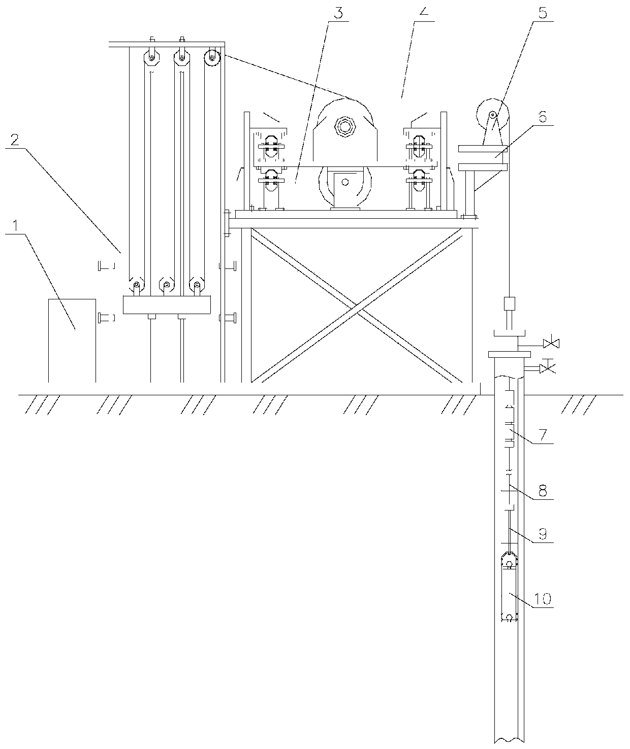
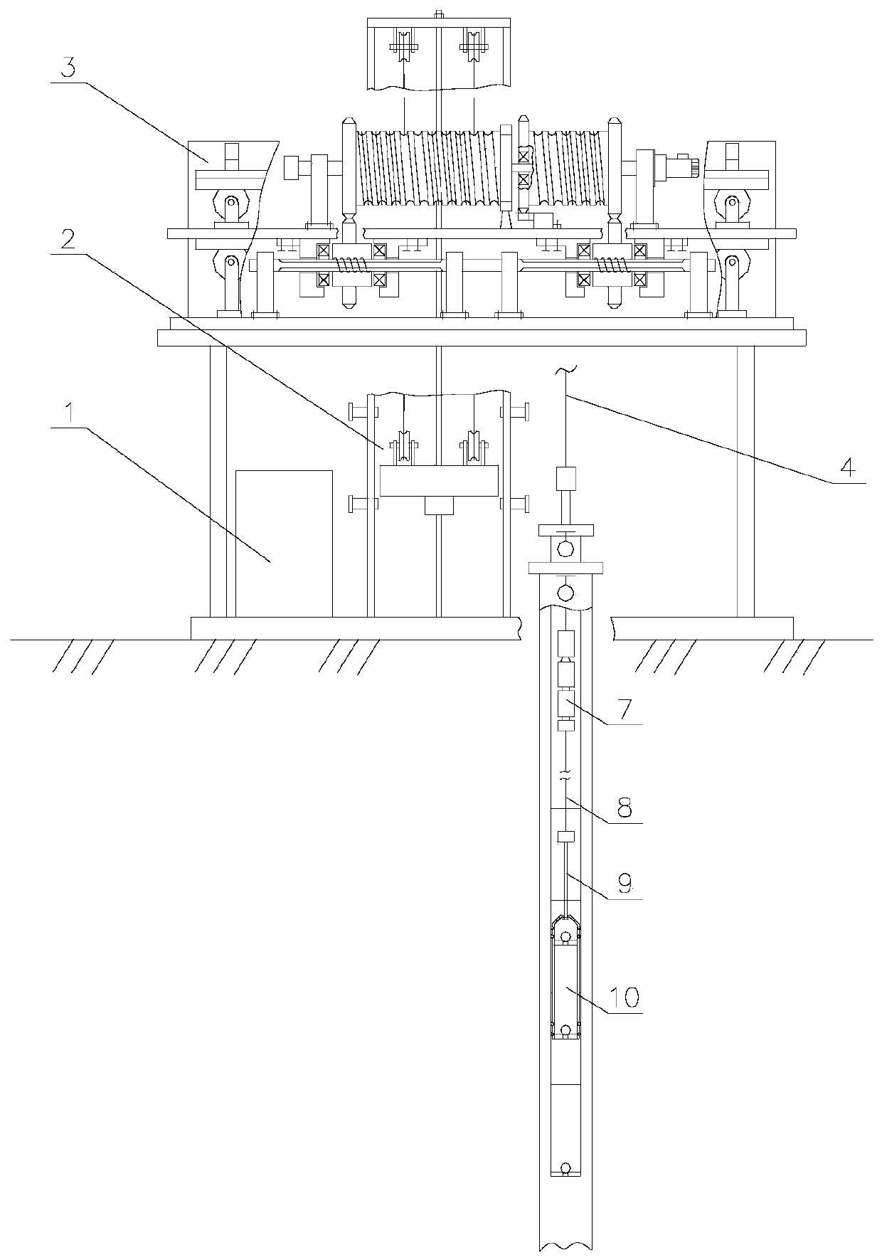
[0029] like Figure 1 to Figure 4 As shown, an intelligent ultra-long stroke pumping unit includes a driving system 3, a flexible polished rod 4 wound on the driving system, a counterweight system connected with the driving system 3, and the output end of the flexible polished rod is wound on a support wheel And connect the rotary shorting 7, the sucker rod 8, the weighting rod 9, and the ultra-long stroke pump 10 in sequence.

[0030] The counterweight system 2 includes a counterweight bracket 11, an anti-falling rod 12, a self-locking device 13, a counterweight block 14, a movable pulley 15, a fixed pulley 16, a wire rope 17, and a support pin 18. The lower end of the counterweight bracket 11 is fixed on the base Up, the support pins 18 are movably installed at the corresponding positions on both sides of the counterweight bracket 11, the lower end of the anti-drop rod 12 is fixed on the base, the anti-drop rod 12 passes through the self-locking device 13 and the hole of the...

Embodiment 2

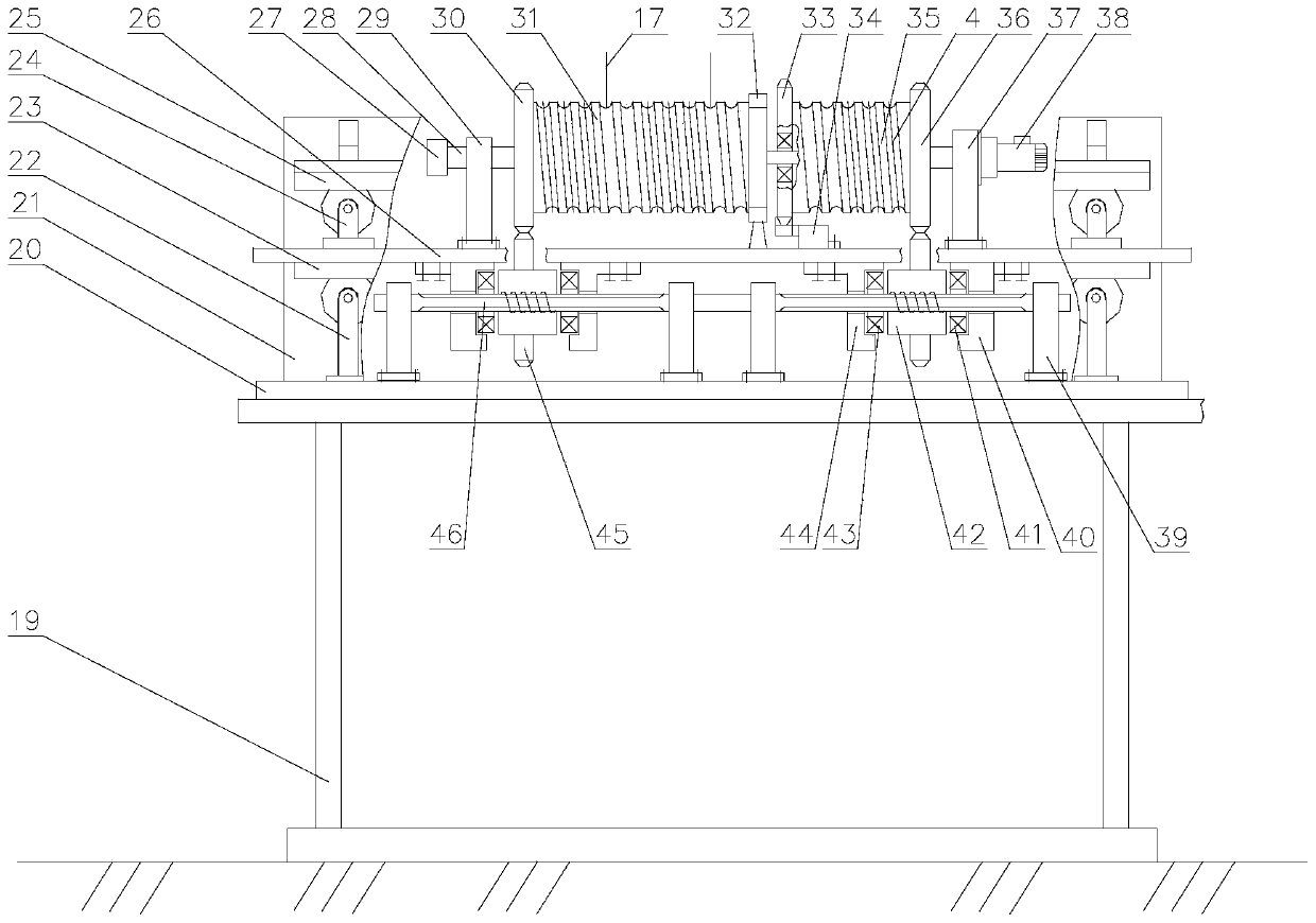
[0043] like Figure 5 As shown, the difference between this embodiment and Embodiment 1 is that the counterweight drum 31 and the hoisting drum 35 are integrated, the middle part is the hoisting drum 35, and the parts on both sides are the counterweight drum 31, and the counterweight drum 31 and the hoisting drum The outer surface of the cylinder 35 is all processed with the same helical direction and is semicircular threaded grooves, the surface of the threaded grooves is melted with wear-resistant, elastic and temperature-resistant non-metallic material, and the pitch of the threaded grooves is consistent with the diameter of the flexible polished rod 4. The two wire ropes in the counterweight system are respectively fixed on the counterweight drum 31 on both sides of the hoisting drum 35, and the rolling bracket 32 ​​is between the hoisting drum 35 and the counterweight drum 31, so that the hoisting pull and the counterweight pulling force can be achieved. balanced.

[004...


PUM


Abstract

The invention relates to an intelligent super-long stroke pumping unit which comprises an electric control cabinet, a driving system, a flexible polish rod winding the driving system and a counterweight system connected to the driving system. The output end of the flexible polish rod winds a supporting wheel and is successively connected to a rotary pup joint, a sucker rod, a weighted lever and asuper-long stroke pump. A regional central control room is connected to the electric control cabinet through a remote data wireless bridge, and the electric control cabinet is connected to the drivingsystem through a cable. The intelligent super-long stroke pumping unit is used for improving the stroke of the pumping unit, eliminating the included angle between the flexible polish rod and a hoisting sheave and prolongs the service life of the polish rod, so that a balance weight of the super-long stroke pumping unit is realized. The super-long stroke pumping unit is further energy-saving. Thepump efficiency, yield, annular liquid level position of an oil jacket can be reflected instantaneously by the electric control cabinet. The oil sucking speed or intermittent oil pumping is adjustedautomatically according to liquid supply data to achieve efficient operation, so that purposes of long stroke, low time of strokes, large displacement, intelligent control, optimized oil extraction, extension of periods of replacing a tube rod and examining the pump and remote digitalized control management are achieved.

Description

technical field [0001] The invention relates to a rod pumping unit of an oil extraction system in the petroleum field, in particular to an intelligent ultra-long stroke oil pumping unit. Background technique [0002] At present, there are rod pump pumping equipment in oilfields, including beam pumping unit, tower pumping unit, and hydraulic pumping unit. The common shortcomings of the above equipment are: the stroke is small, the maximum stroke does not exceed 10 meters, the stroke times are high, and the average stroke is high. The stroke is about 6 times per minute, and the stroke times of individual pumping units are up to 9 times per minute, and the displacement is low. Due to the small stroke and high stroke times, the time for the oil to enter the pump is short, resulting in insufficient fullness of the pumping pump. All are accompanied by shock loads, low pump efficiency and system efficiency, large wear of rods, pipes, and pumps, frequent pump inspections, and high m...

Claims


Application Information

Patent Timeline
Patent Type & Authority Applications(China)
IPC IPC(8): E21B43/00
CPCE21B43/126
Inventor 沃森·埃里克
Owner 沃森埃里克
Learn More