A method and device for adapting light source parameters in a distributed optical fiber sensing system

A technology of distributed optical fiber and sensing system, which is applied in measuring devices, thermometers with physical/chemical changes, instruments, etc., can solve problems such as system performance degradation, cumbersome steps, corrosion, etc., and achieve optimal system response time and system The effect of high performance stability and strong system adaptability

Active Publication Date: 2021-11-16
BEIJING INST OF AEROSPACE CONTROL DEVICES
View PDF5 Cites 1 Cited by
  • Summary
  • Abstract
  • Description
  • Claims
  • Application Information

AI Technical Summary

Problems solved by technology

If the repetition frequency of the detection light pulse is too slow, the single measurement time will increase, and the response time will increase significantly after accumulation and averaging, which is not conducive to fire detection and other applications that require high response time
At the same time, for different applications, different lengths and types of optical fibers are often used. The relevant parameters of the distributed optical fiber sensing system need to be manually debugged and modified, and the steps are cumbersome. , and it needs to be re-debugged and modified, and the later maintenance work is relatively large
In addition, the loss in the optical fiber is prone to change under the influence of the external environment for a long time
For example, after the long-term operation of the downhole optical cable, it is corroded by hydrogen ions and the loss increases. If the power of the incident detection optical pulse cannot be adjusted in time, the system performance will be greatly reduced.

Method used


Image

  • A method and device for adapting light source parameters in a distributed optical fiber sensing system
  • A method and device for adapting light source parameters in a distributed optical fiber sensing system
  • A method and device for adapting light source parameters in a distributed optical fiber sensing system

Examples


Embodiment 2

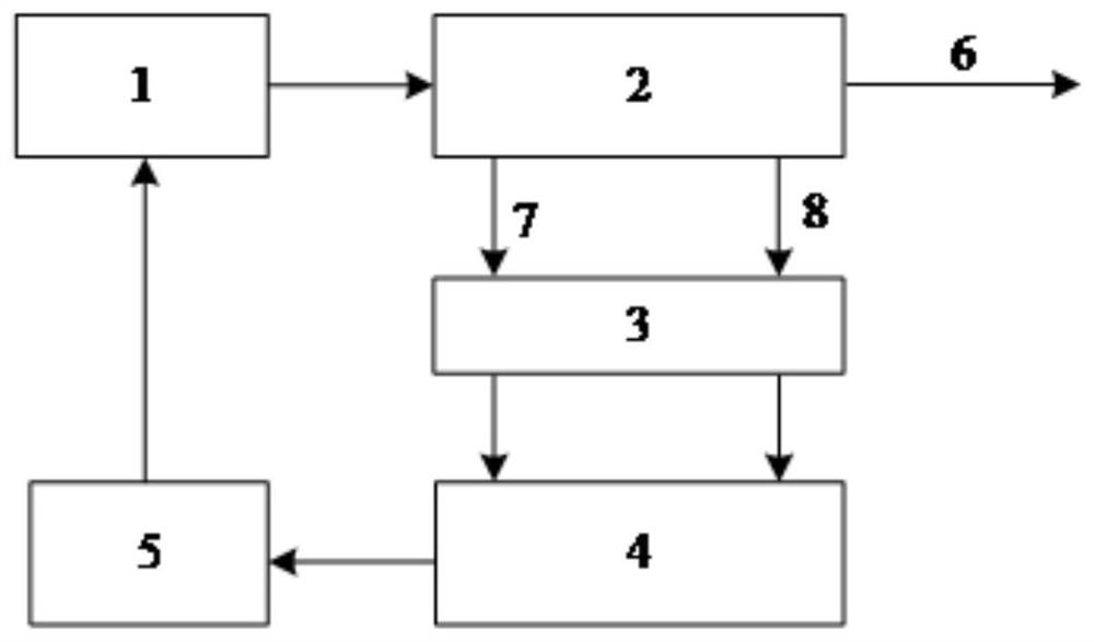
[0046] Such as figure 2 , on the basis of the above embodiments, the present invention also discloses a device for adapting light source parameters of a distributed optical fiber sensing system, including: a detection light pulse generating device 1, an optical fiber wavelength division multiplexer 2, and a photoelectric conversion module 3 , a signal acquisition and processing module 4 , a microcontroller 5 and a sensing fiber 6 . Wherein, the pulsed fiber laser 1 sends a laser pulse signal; the laser pulse is injected into the sensing fiber 6 through the fiber wavelength division multiplexer 2, and the laser pulse signal will generate a spontaneous pull when it is transmitted in the sensing fiber 6. Mann backscattered light; the spontaneous Raman backscattered light is split into Raman Stokes scattered light 7 and anti-Stokes light 8 by the fiber wavelength division multiplexer 2; The optoelectronic signal conversion is completed through the photoelectric conversion module...


PUM


Abstract

The invention discloses a method and device for self-adapting the light source parameters of a distributed optical fiber sensing system. , adjust the optical pulse repetition frequency; Step S2, calculate the standard deviation of the point scattering signal S(L-m)~S(L-n) at the end of the sensing fiber in t measurement periods, and filter to obtain the maximum value of the standard deviation σ max ; Step S3, set σ max and set the default value σ 0 Compare; step S4, if σ max >σ 0 , then increase the output power of the light source, and repeat steps S2-S3 until σ max ≤σ 0 . The invention can monitor the standard deviation of the signal at the tail end of the sensing fiber in real time. The repetition frequency of the pulsed laser is modified in real time by the microcontroller to optimize the system response time. The measured standard deviation is compared with the preset standard deviation. When the measured standard deviation is found to be less than the preset value, the output power of the light source is increased through the microcontroller to improve the signal-to-noise ratio and eliminate the performance degradation caused by the increase in fiber loss.

Description

technical field [0001] The invention belongs to the technical field of optical fiber sensing, and in particular relates to a method and a device for self-adapting light source parameters of a distributed optical fiber sensing system. Background technique [0002] Optical fiber sensing technology has gradually become one of the most representative emerging technologies in the field of sensing due to its passive sensing medium, corrosion resistance, anti-electromagnetic interference, and long service life. Among them, distributed optical fiber sensing technology uses optical time domain reflection technology to locate the backscattered signal at any point in the optical fiber. Therefore, it has the function of measuring the distribution of physical quantities along the optical fiber. The monitoring of relevant physical quantities in the range of several kilometers or even tens of kilometers can be realized through a single optical fiber. The backscattering signal in the optic...

Claims


Application Information

Patent Timeline
Patent Type & Authority Patents(China)
IPC IPC(8): G01K11/32G01K11/324
CPCG01K11/32G01K11/324
Inventor 朱晓非杨潇君李娜杜瑞潘亮
Owner BEIJING INST OF AEROSPACE CONTROL DEVICES
Why Eureka
Try Eureka