
Roof prism machining technology

A technology of roof prism and processing technology, which is applied in the direction of metal processing equipment, manufacturing tools, work carriers, etc., can solve the problems of low production efficiency, pass rate and product precision, achieve efficiency improvement, improve product precision, pass rate and precision Improved effect

Active Publication Date: 2020-04-28
马鞍山市江南光学有限公司
View PDF6 Cites 6 Cited by
  • Summary
  • Abstract
  • Description
  • Claims
  • Application Information

AI Technical Summary

Problems solved by technology

[0006] Aiming at the problems of low production efficiency, qualified rate and product precision of the existing rectangular roof prism production process, the present invention provides a roof prism processing process, each surface is processed in place at one time, the production process is reduced by nearly half, and the efficiency is increased by about At the same time, the superposition of human error in the two processes of grinding and polishing is reduced. In addition, before processing the right-angled surface and the roof surface, the surface of the side and the roof edge is firstly processed, and these two surfaces are used as the reference plane The right-angled surface and the roof surface are processed by positioning, which greatly improves the product accuracy and qualification rate

Method used


Image

  • Roof prism machining technology
  • Roof prism machining technology
  • Roof prism machining technology

Examples


Embodiment 1

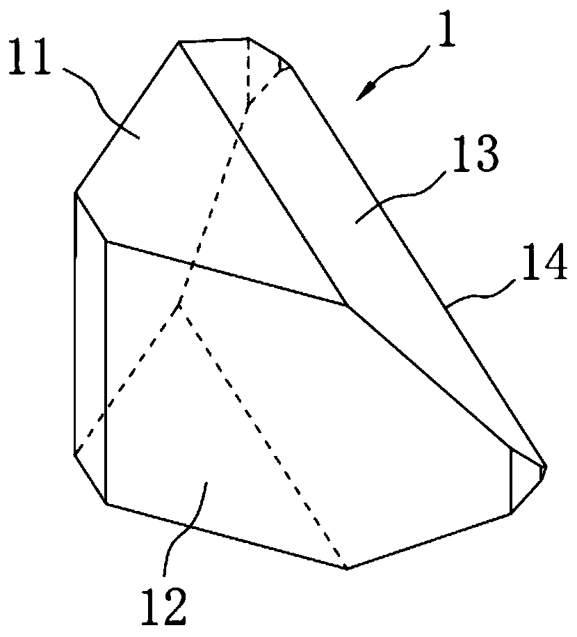
[0051] A kind of roof prism processing technology in this embodiment is specially used in processing production such as figure 1 The roof prism 1 shown in , the roof prism 1 is an isosceles right-angle roof prism, including two side surfaces 11, two mutually perpendicular right-angle surfaces 12 and two mutually perpendicular roof surfaces 13, the two roof surfaces 13 intersect to form a roof prism 14. The production and processing steps are as follows:

[0052] S01, take the roof prism wool, first grind and process two sides 11; the roof prism wool is an isosceles right-angle prism;

[0053] S02, grinding and polishing the large surface of the roof prism wool, and processing the surface where the roof prism 14 is located, which is the large surface of the processed roof prism wool;

[0054] S03, using the surface of the roof ridge 14 for positioning, grinding and polishing to process two right-angled surfaces 12;

[0055] S04 , using the side surfaces 11 for positioning, g...

Embodiment 2

[0059] A kind of roof prism processing technology in this embodiment, the basic steps are the same as embodiment 1, the difference and improvement are that the processing steps of the side 11 are:

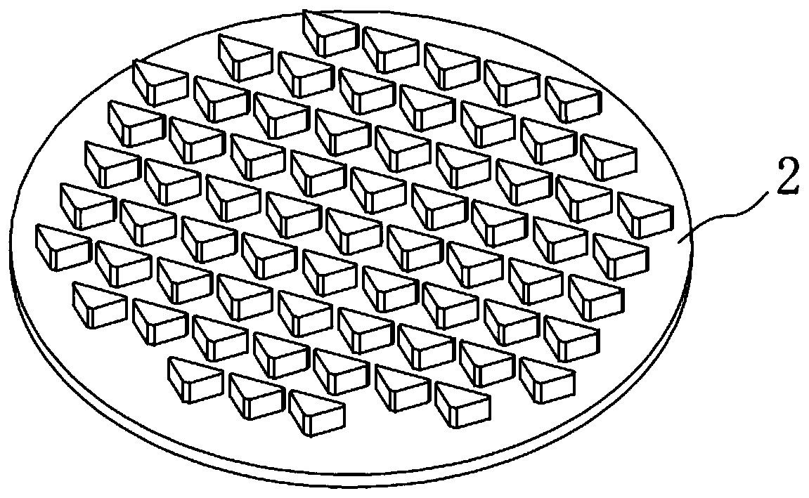
[0060] i. Wipe one side of the roof prism wool with acetone reagent, then place it on the tray 2 with this side facing down, and drop optical glue on the lower end of the roof prism wool to fix it, and let it stand for about 10 minutes until The glue is completely dry, and protective paint is smeared around the roof prism wool to prevent water from seeping into the ground of the roof prism wool during subsequent processing, causing the roof prism wool to fall off from the pallet 2; the pallet described in this embodiment 2 has a diameter of 300mm, and each tray can place about 100 pieces of said roof prism wool;

[0061] ⅱ, such as figure 2 As shown in , place the entire tray 2 evenly on the two-axis machine, and grind the side facing the roof prism wool from top to bottom, with ...

Embodiment 3

[0066] A kind of roof prism processing technique in the present embodiment, basic steps are the same as embodiment 1 and 2, difference and improvement are that, the processing steps of the surface where described roof ridge 14 is:

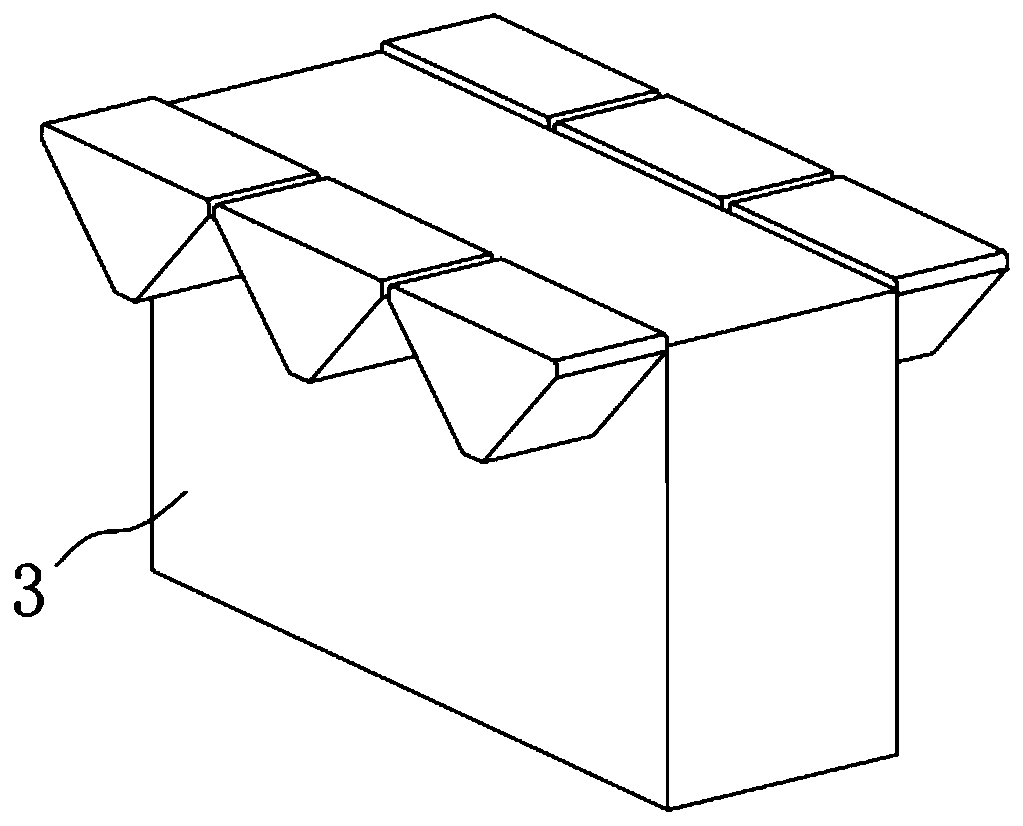
[0067] ⅰ, such as image 3 As shown in , prepare a backing body I3 with length×width×height=75mm×25mm×50mm, and glue one of the side surfaces 11 to the side of the backing body I3 with optical glue to ensure that the large surface of the roof prism wool is horizontally facing On and higher than the upper end of the body I3, 6 pieces are fixed on each body I3, and then the lower end of the body I3 is fixed on the tray 2 with optical glue, and 10 pieces are fixed on each plate;

[0068] ⅱ. Place the full tray 2 evenly and put the whole tray in the two-axis machine, and grind the large surface of the roof prism wool from top to bottom. The grinding size error is controlled within 0.005mm, and the surface flatness is controlled within 0.001mm , the pa...


PUM

PropertyMeasurementUnit
Diameteraaaaaaaaaa

Abstract

The invention discloses a roof prism machining technology, and relates to the technical field of roof prism machining. The technology comprises the following machining steps that S01, a roof prism blank is taken, and firstly the blank is ground to be provided with two side surfaces; S02, a large surface of the roof prism blank is ground and polished, and a surface where a roof ridge is located ismachined; S03, the surface where the roof ridge is located is used for positioning, and grinding and polishing are conducted to obtain two right-angle surfaces; and S04, the side surfaces are used forpositioning, and grinding and polishing are carried out to obtain two roof ridge surfaces. According to the technology, each surface is machined in place at a time, the production procedures are reduced by nearly a half, the efficiency is improved by about one time, meanwhile, superposition of manual operation errors in the grinding process and the polishing process is reduced, in addition, the surfaces where the side surfaces and the roof ridge are located are subjected to finish machining before the right-angle surfaces and the roof ridge surfaces are machined, the two surfaces serve as reference faces to be used for positioning and machining the right-angle surfaces and the roof ridge surfaces, and the product precision and the percent of pass are greatly improved.

Description

technical field [0001] The invention relates to the technical field of roof prism processing, in particular to a roof prism processing technology. Background technique [0002] The right-angled roof prism is a reflective prism that replaces the large surface of the right-angled prism with two mutually perpendicular reflecting surfaces. . Right-angle roof prisms can invert and deflect the image by 90°, that is, when passing through the prism, the outgoing ray is perpendicular to the incoming ray, and the image is reflected from right to left and top to bottom. Therefore, right-angle roof prisms are mainly used to reflect light in optical imaging systems, which are not limited by the critical angle of total reflection and can accept incident light with a larger angle. [0003] The traditional method of producing right-angled roof prisms is: first use the right-angled prism wool to grind a blank with the same shape and size as the product, and then polish the right-angled sur...

Claims


Application Information

Patent Timeline
IPC IPC(8): B24B1/00B24B13/005B24B13/01B24B37/27
CPCB24B1/00B24B13/005B24B13/01B24B37/27
Inventor 金正彬
Owner 马鞍山市江南光学有限公司
Learn More