Signal isolation transmission circuit

A signal isolation and transmission circuit technology, applied in logic circuits, logic circuit coupling devices, logic circuit interface devices, etc., can solve problems such as cost, volume, increased design complexity, transformer volume, and complex production processes and obstacles.

Active Publication Date: 2020-04-28
MORNSUN GUANGZHOU SCI & TECH
View PDF4 Cites 5 Cited by
  • Summary
  • Abstract
  • Description
  • Claims
  • Application Information

AI Technical Summary

Problems solved by technology

[0007] The key technical point is that the signal coupling transformer works in push-pull mode, which needs to be completed by a total of four windings on the primary and secondary sides. Therefore, the number of windings in the transformer is large, and the volume

Method used


Image

  • Signal isolation transmission circuit
  • Signal isolation transmission circuit
  • Signal isolation transmission circuit

Examples


no. 1 example

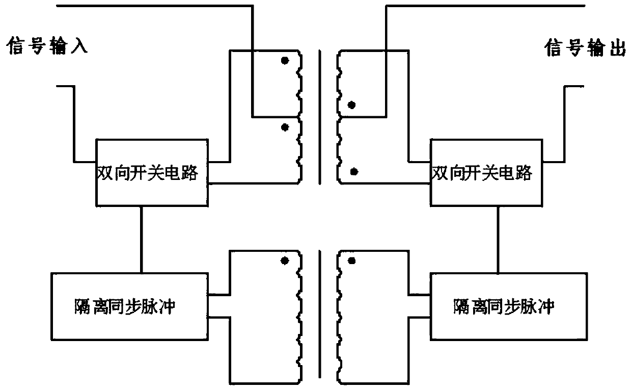
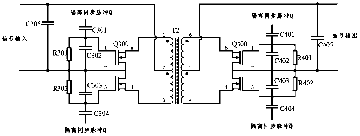
[0043] Figure 4 It is the circuit principle diagram of the signal isolation transmission circuit of the first embodiment of the present invention, such as Figure 4 As shown, compared with the background technology figure 2The difference of the technical solution shown in is that: in the application of the background technology, the signal coupling transformer works in the push-pull mode, and the excitation and demagnetization of the transformer need to be completed by alternating conduction of the two windings on the primary side, so the number of windings of the transformer More, the adverse effect is that the volume of the transformer and the production process are relatively complicated, which is unfavorable for process automation; in the application circuit of the present invention, the input DC signal can be converted into an AC signal through the drive signal and the chopper circuit, so that the signal coupling transformer Signal coupling is done in the case of a sin...

no. 2 example

[0065] Figure 6 It is the circuit schematic diagram of the signal isolation transmission circuit of the second embodiment of the present invention, such as Figure 6 As shown, the difference from the first embodiment is that the signal chopping circuit includes a MOS transistor Q20, an inverter U21D, resistors R20, R21, R22, a capacitor C20, a C21 diode D20.

[0066] The connection relationship is: the positive input terminal of U10A is connected to the input DC signal, the negative input terminal of U10A is connected to the output terminal of U10A, the output terminal of U10A is connected to the resistor R10, the other end of R10 is connected to R11 and the positive input terminal of U10B, and one end of R11 is connected to the positive input terminal of U10B. Input terminal, the other end of R11 is connected to the input DC signal reference ground GND1, the negative input terminal of U10B is connected to R12 and R13, one end of R12 is connected to the negative input termina...


PUM


Abstract

The invention provides a signal isolation transmission circuit, and the circuit comprises an input signal conversion circuit used for carrying out proportional operation on a direct current input voltage signal; a signal chopper circuit which is used for converting the direct current voltage signal into a positive and negative voltage square wave pulse signal; a signal coupling circuit which is used for isolating and coupling the positive and negative voltage square wave pulse signal; a signal restoring circuit which is used for restoring the positive and negative voltage square-wave pulse signals into direct-current voltage signals; and an output signal conversion circuit which is used for proportionally amplifying the voltage signal generated by the reduction circuit and outputting the amplified voltage signal. According to the invention, a direct-current input voltage signal in the circuit is converted into a positive and negative bipolar model after passing through the chopper circuit, single-winding signal isolation transmission of the signal isolation transformer in the signal coupling circuit can be realized, and the number of windings and the number of turns of the transformer can be greatly reduced, so the size of the transformer is reduced, the production process difficulty is reduced, and the production cost is greatly reduced.

Description

technical field [0001] The invention relates to signal isolation and transmission in the industrial measurement and control industry, in particular to an isolation transmission circuit for DC voltage signals. Background technique [0002] In the industrial measurement and control industry, the signal isolation transmitter is one of the current signal isolation applications. The patent number is ZL200910038270.0, and the public date is September 9, 2009. The name is "A DC Bipolar Signal Isolation Conversion The method and its circuit of the "patent document" discloses an isolation conversion method and its circuit, such as figure 1 As shown, the isolated transmission circuit includes a first bidirectional switch circuit, a synchronous pulse circuit, a coupling transformer, and a second bidirectional switch circuit. [0003] Its circuit structure is: the primary winding of the isolation coupling transformer is connected with the first bidirectional switching device to form an...

Claims


Application Information

Patent Timeline
IPC IPC(8): H03K19/0175H03K19/01
CPCH03K19/017509H03K19/017545H03K19/01
Inventor 马涛
Owner MORNSUN GUANGZHOU SCI & TECH
Why Eureka
Try Eureka