Switching value signal transmission control system based on optical fiber

A switching signal, transmission control technology, applied in the direction of optical fiber transmission, transmission system, electromagnetic wave transmission system, etc., can solve the problems of susceptibility to electromagnetic interference, impossibility of path self-inspection, cumbersome transmission cables, etc., to achieve fixed-point monitoring, complex Powerful, small size effect

Pending Publication Date: 2020-04-28
UNIV OF ELECTRONICS SCI & TECH OF CHINA
View PDF0 Cites 1 Cited by
  • Summary
  • Abstract
  • Description
  • Claims
  • Application Information

AI Technical Summary

Problems solved by technology

[0004] In order to solve the problems of cumbersome transmission cables, inaccessible path self-inspection, and susceptibility to electromagnetic interference in the transmission of a large number of switching signals in the current industrial process measurement and control system; the present invention proposes a fiber-based switching signal transmission control system, Using the advantages of small size of optical fiber, anti-electromagnetic interference, and strong multiplexing ability to realize a switching value transmission control system with a simple transmission path and self-inspection of the path

Method used


Image

  • Switching value signal transmission control system based on optical fiber
  • Switching value signal transmission control system based on optical fiber
  • Switching value signal transmission control system based on optical fiber

Examples


Embodiment 1

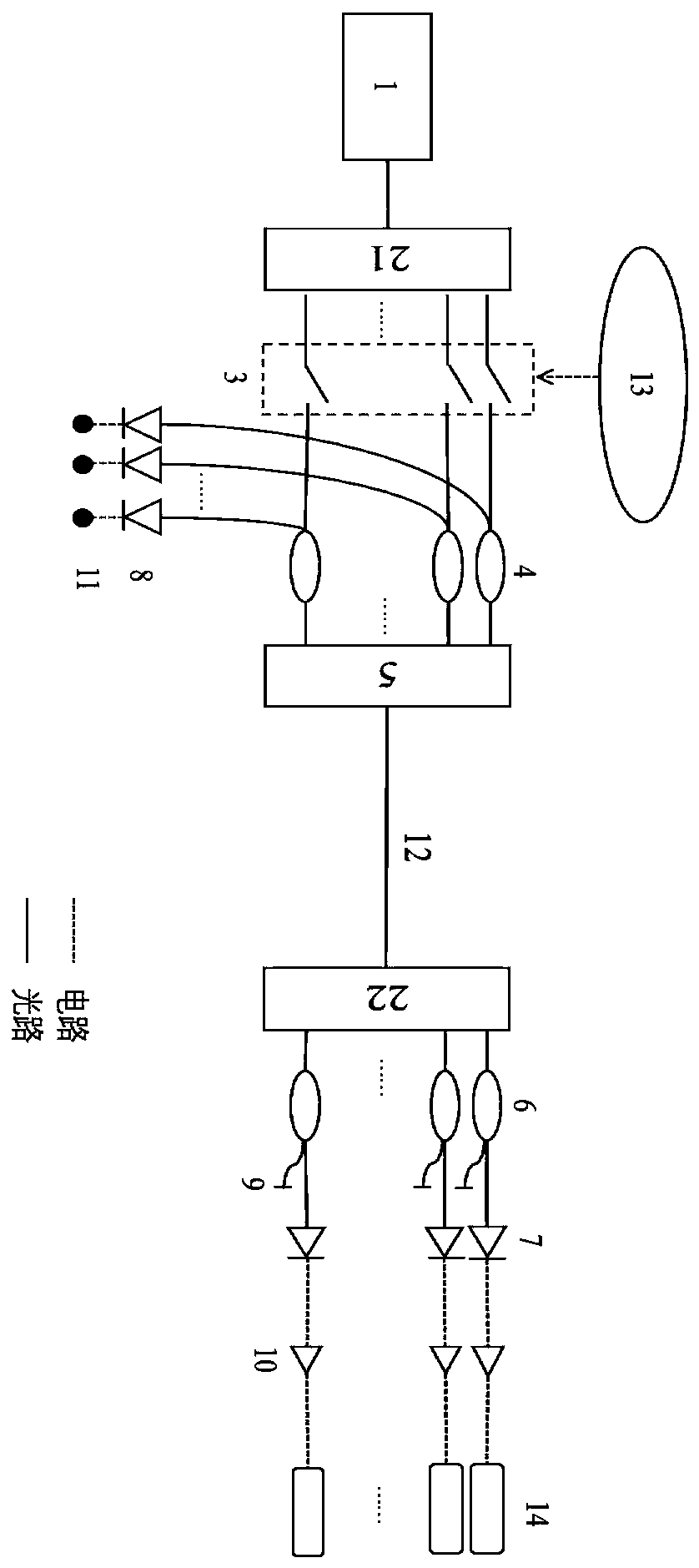
[0036] The implementation of the light source generation module is: including: a broadband light source, a second 1*n wavelength division multiplexer, and the broadband light source generates n optical signals of different wavelengths through the second 1*n wavelength division multiplexer; figure 1 As shown, the optical fiber-based switch signal transmission control system of the present invention includes: broadband light source 1, two 1*n wavelength division multiplexers 21, 22, optical switch 3, 2*1 coupler 4, n*1 Wavelength division multiplexer 5, 1*2 splitter 6, two groups containing n photodetectors 7, 8, mirror 9, voltage amplifier 10, light emitting diode 11, transmission fiber 12, circuit or manual switch signal output System 13, switch valve or relay 14;

[0037] The working principle is: the broadband light source 11 is divided into n optical paths with different wavelengths through a 1*n wavelength division multiplexer 21, and connected to n optical switches contro...

Embodiment 2

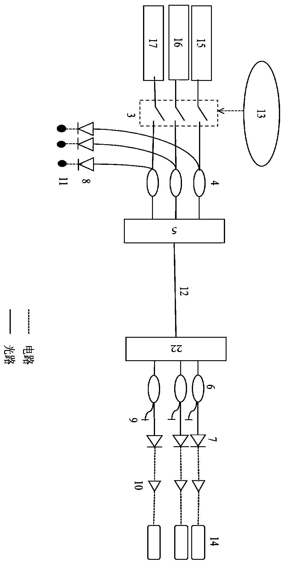
[0039] In order to facilitate the understanding of the content of the present invention, the value of n is 3 in this embodiment.

[0040] The implementation of the light source generation module is as follows: the broadband light source 1 and the 1*3 wavelength division multiplexer 21 described in Embodiment 1 are replaced by multiple single-wavelength light sources with different wavelengths; figure 2As shown, the optical fiber-based switching signal transmission system of the present invention includes: single-wavelength light sources 15, 16, 17, 1*3 wavelength division multiplexers 22, optical switches 3, 2*1 couplers 4, 3*1 Wavelength division multiplexer 5, 1*2 splitter 6, two groups containing n photodetectors 7, 8, mirror 9, voltage amplifier 10, light emitting diode 11, transmission fiber 12, circuit or manual switch signal output System 13, switch valve or relay 14;

[0041] The three single-wavelength light sources 15, 16, and 17 containing different wavelengths ar...


PUM


Abstract

The invention discloses a switching value signal transmission control system based on an optical fiber, which is applied to the field of optical fiber communication, and aims to solve the problems ofcomplicated transmission cables, easiness in electromagnetic interference, difficulty in access self-inspection and the like in transmission of a large number of switching value signals in an industrial process measurement and control system. According to the invention, optical signals with different wavelengths are adopted to independently transmit different switching value signals; optical signals carrying different switching value signals are transmitted through an optical fiber. Before entering a control system, optical signals carrying different switching value signals are converted intoa plurality of corresponding electric signals through a plurality of second photoelectric detectors, the electric signals carry different switching value signals, the electric signals are amplified through a voltage amplifier and then input into a switching valve or a relay, and transmission of a large number of switching value signals is achieved. Before entering the second photoelectric detector, optical signals carrying different switching value signals are simultaneously reflected back to the first photoelectric detector through the reflecting mirror and converted into electric signals tobe output to the semiconductor diode, and access self-checking is achieved.

Description

technical field [0001] The invention belongs to the technical field of optical fiber communication, and in particular relates to a switching value transmission control system. Background technique [0002] Industrial process measurement and control systems require a large number of switching signal transmissions. Most of the traditional transmission methods use the on-off of 24V or 48V electrical signals to transmit switching signals. This method requires a large number of cables and is not easy to carry out multi-terminal Isolation distribution makes it difficult to conduct path self-test, and there are also certain deficiencies in electromagnetic compatibility. [0003] Optical fiber has the advantages of small size, anti-electromagnetic interference, and strong multiplexing ability, which can realize simultaneous and independent transmission of multiple signals on one optical fiber. Contents of the invention [0004] In order to solve the problems of cumbersome transmi...

Claims


Application Information

Patent Timeline
Patent Type & Authority Applications(China)
IPC IPC(8): H04B10/25H04J14/02H04B10/079
CPCH04B10/079H04J14/0202
Inventor 冉曾令何秀何正熙朱加良何鹏
Owner UNIV OF ELECTRONICS SCI & TECH OF CHINA
Why Eureka
Try Eureka