In-situ detection system for straight section distribution of petroleum hydrocarbon contaminants at contaminated sites

A vertical profile and in-situ detection technology, applied in the electromechanical field, can solve the problems of in-situ detection of petroleum hydrocarbons on site, cumbersome steps, secondary pollution, etc., and achieve high-efficiency detection technology and equipment for vertical profile distribution of petroleum hydrocarbon pollution on site , Improve detection efficiency, and environmental friendliness

Active Publication Date: 2020-05-01
HEFEI INSTITUTES OF PHYSICAL SCIENCE - CHINESE ACAD OF SCI
View PDF4 Cites 8 Cited by
  • Summary
  • Abstract
  • Description
  • Claims
  • Application Information

AI Technical Summary

Problems solved by technology

However, such laboratory methods usually use complex extraction methods such as ultrasound and vibration, which require the use of certain toxic organic solvents. The detection time is long, the steps are cumbersome, and it is easy to cause secondary pollution. On-site detection of petroleum hydrocarbons cannot be realized. Its timeliness cannot meet the needs of site remediation for real-time in-situ detection technology of vertical distribution of petroleum hydrocarbon pollution
Existing technologies still require a complex sampling process for deep soil, which requires drilling rigs to take samples from soil layers at different depths and then measure them. It is impossible to realize real-time and in-situ detection of the vertical profile distribution of petroleum hydrocarbon pollutants on site

Method used


Image

  • In-situ detection system for straight section distribution of petroleum hydrocarbon contaminants at contaminated sites
  • In-situ detection system for straight section distribution of petroleum hydrocarbon contaminants at contaminated sites

Examples


Embodiment Construction

[0011] The present invention will be further described below in conjunction with the accompanying drawings and specific embodiments.

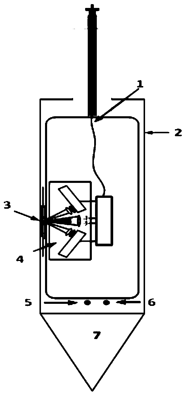
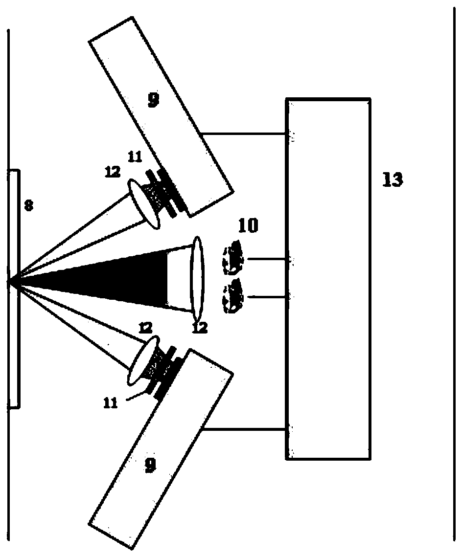
[0012] Such as Figure 1-2 As shown, an in-situ detection system for the vertical profile distribution of petroleum hydrocarbon pollutants in a polluted site of the present invention includes a casing 2, a fluorescence excitation and detection module 4, a drill bit 7, a detection window 3, and a conductivity sensor 6.

[0013] The casing 2 and the drill bit 7 constitute the casing of the in-situ detection system for the vertical profile distribution of petroleum hydrocarbon pollutants in the polluted site, wherein the drill bit 7 is mainly used for drilling the ground and carrying the system into soil layers of different depths, and the casing 2 is mainly used for the inside of the system Device protection. The detection window 3 is on the casing 2, and its main body is made of quartz glass in order to ensure the sensitivity and accuracy of fl...


PUM


Abstract

The invention discloses an in-situ detection system for straight section distribution of petroleum hydrocarbon contaminants at contaminated sites, and creates an in situ detection system for straightsection distribution of petroleum hydrocarbon contaminants at contaminated sites based on the induced fluorescence technology aiming at urgent needs for the real-time in-situ measurement technology ofstraight section distribution of contaminants, such as treatment and restoration of contaminated sites, and contaminated situation survey for the sites. The invention uses high-energy ultraviolet LEDs of 270nm and 320nm to in-situ excite the petroleum hydrocarbon contaminants in the deep of the contaminated sites to detect fluorescence signals with the wavelengths of 350nm and 450nm, and uses a characteristic fluorescence spectrum of petroleum hydrocarbon to invert the concentration of the contaminants in real time to realize real-time and in-site detection of straight section distribution ofpetroleum hydrocarbon contaminants at sites. The invention has a cylindrical shell and a drill bit that can drill deep into the soil using a soil drill. In the process of using the technology, thereis no need of a reagent, no secondary pollution, and no tedious sample pretreatment and detection process, which can significantly improve the efficiency of the detection of petroleum hydrocarbon pollution at sites.

Description

technical field [0001] The invention belongs to the fields of electromechanical technology, spectrum analysis technology and environmental pollution detection, and in particular relates to an in-situ detection system for the vertical profile distribution of petroleum hydrocarbon pollutants in polluted sites. Background technique [0002] Petroleum hydrocarbon pollutants on site have long been the focus of supervision by the environmental protection department. Currently, on-site sampling-laboratory analysis methods based on infrared spectrophotometry, high performance liquid chromatography, and gas chromatography are mainly used for petroleum hydrocarbon pollutants in industrially polluted sites. Chemical indicators analyze the type and content of pollutants. This type of method is widely adopted by countries all over the world. In the "National Soil Pollution Survey Sample Analysis and Determination Technical Regulations" compiled by my country's State Environmental Protect...

Claims


Application Information

Patent Timeline
Patent Type & Authority Applications(China)
IPC IPC(8): G01N21/64G01N21/27
CPCG01N21/6402G01N21/274G01N2021/6463Y02A50/20
Inventor 孟德硕赵南京马明俊殷高方杨瑞芳方丽甘婷婷黄尧左兆陆
Owner HEFEI INSTITUTES OF PHYSICAL SCIENCE - CHINESE ACAD OF SCI
Why Eureka
Try Eureka