Design method of slow wave structure of strip-shaped beam traveling wave tube working in high-order mode

A slow-wave structure and high-order mode technology, which is applied in the field of microwave electronics and terahertz, can solve the problems of reduced electronic channel width and limited power capacity of strip-shaped injection traveling wave tubes, so as to increase practicability, increase power capacity, and design cycle short effect

Active Publication Date: 2020-05-12
UNIV OF ELECTRONIC SCI & TECH OF CHINA
View PDF10 Cites 3 Cited by
  • Summary
  • Abstract
  • Description
  • Claims
  • Application Information

AI Technical Summary

Problems solved by technology

However, as the frequency rises to millimeter waves, the size co-transition effect makes the electron channel width of the stripped traveling wave tube greatly red

Method used


Image

  • Design method of slow wave structure of strip-shaped beam traveling wave tube working in high-order mode
  • Design method of slow wave structure of strip-shaped beam traveling wave tube working in high-order mode
  • Design method of slow wave structure of strip-shaped beam traveling wave tube working in high-order mode

Examples


Embodiment Construction

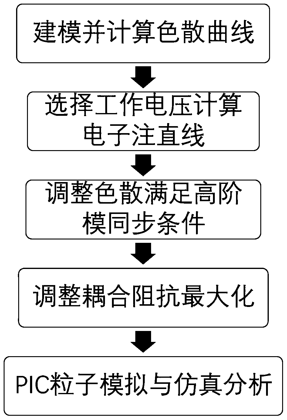
[0027] Below in conjunction with accompanying drawing, the present invention is further described:

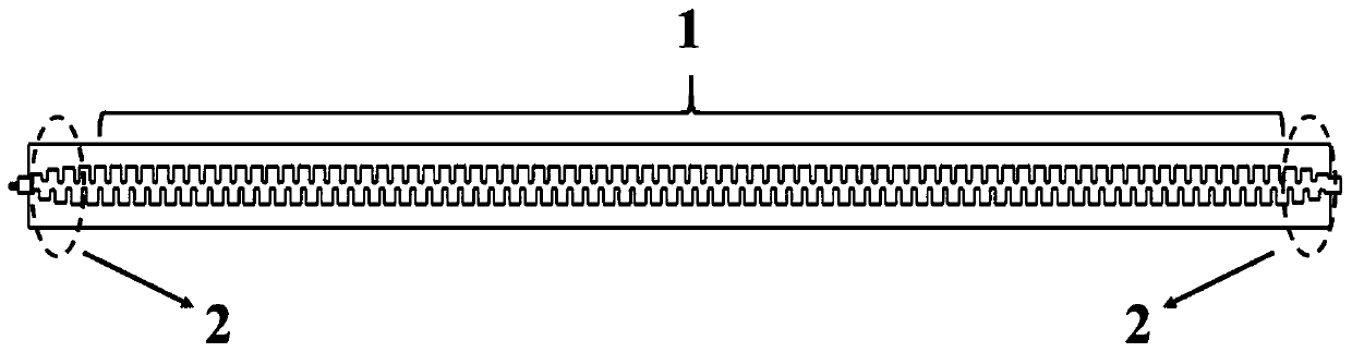
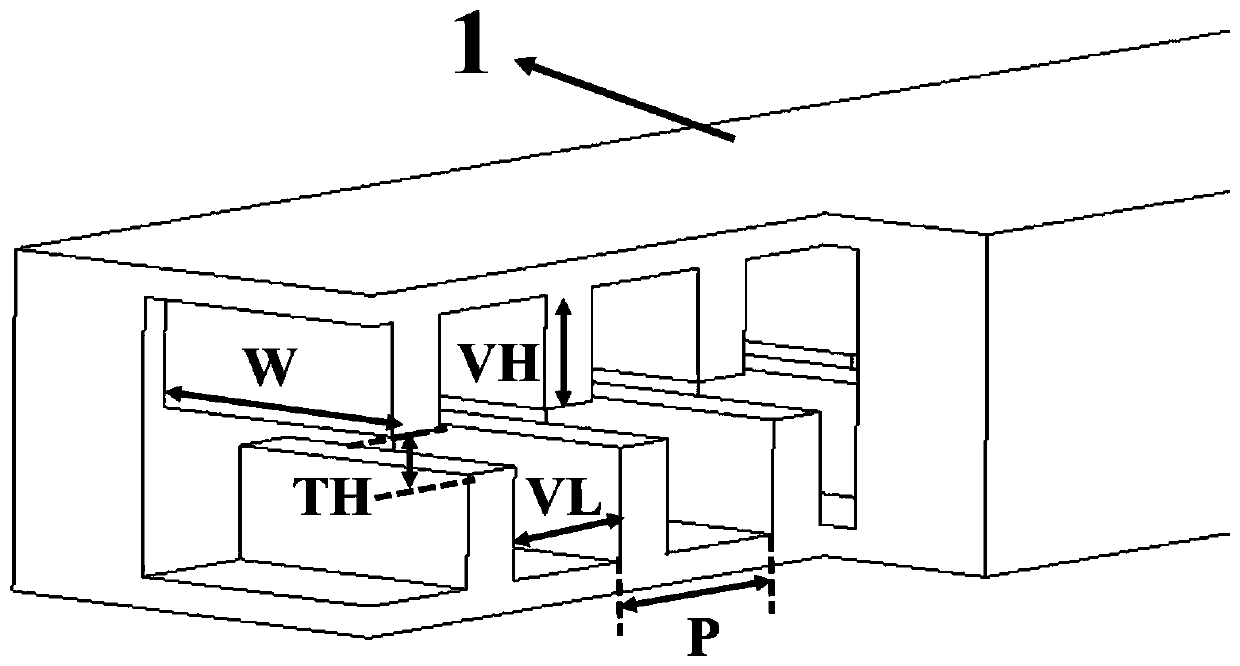
[0028] Refer to attached figure 1 , the design method of the slow-wave structure of a strip-shaped injection traveling wave tube of a kind of high-order mode work of the present embodiment, comprises the following steps: provide initial model (the width W of its slow-wave structure cross-section and the electron channel height TH are respectively 770 μ m and 150 μm. The period length P of the slow wave structure is 468 μm, the spacing VL between two adjacent grids on the same side is 351 μm, and the grid height VH is 320 μm), and the dispersion curve is modeled and calculated using software HFSS. On this basis, modify the electronic channel, staggered gate width and height parameters to ensure that the required bandwidth is met in the working frequency band and at the same time have the maximum electron beam width. At this time, the adjusted slow wave structure cross-section wi...


PUM


Abstract

The invention discloses a design method of a strip beam traveling wave tube slow wave structure working in a high-order mode, and relates to the technical field of microwave electronics and terahertz.The design method has the advantages that the strip beam traveling wave tube is enabled to successfully work in a high-order mode, limitation of cut-off frequency on the width of an electron channelis eliminated, the advantage of large width of strip beam electrons is brought into full play, and the power capacity of the strip beam traveling wave tube is greatly increased. Meanwhile, due to thefact that the size is enlarged, the machining and assembling difficulty is further reduced, a device can work under the large voltage, the interaction impedance is improved, and the electron beam andelectromagnetic wave transduction efficiency is improved. Compared with a traveling wave tube with a circular section electron beam in a traditional working mode, the power capacity is improved by oneorder of magnitude.

Description

technical field [0001] The invention relates to the fields of microwave electronics and terahertz technology, in particular to a design method of an interlaced grating-shaped injection traveling wave tube working in a high-order mode. Background technique [0002] As we all know, a series of superior characteristics of terahertz wave make it have very important academic and application value (some are already in the practical stage). This has also made countries all over the world pay great attention to the research and application of terahertz science and technology, mainly in the United States, Europe and Japan. The general consensus reached in China: Terahertz technology provides an excellent opportunity for scientific and technological innovation, national economic development, national security construction, etc., and may lead to the revolutionary development of science and technology. [0003] At present, the most important factor limiting the development of terahertz...

Claims


Application Information

Patent Timeline
IPC IPC(8): G06F30/25H01J25/34H01J23/24
CPCH01J25/34H01J23/24
Inventor 王建勋万易鑫罗勇
Owner UNIV OF ELECTRONIC SCI & TECH OF CHINA
Why Eureka
Try Eureka