
Mobile robot positioning method based on RGB-D camera and IMU information fusion

A mobile robot and positioning method technology, which is applied in the directions of instruments, surveying and navigation, measuring devices, etc., can solve the problems of divergent pose, positioning accuracy only at the decimeter level, and large volume, and achieves good dynamic characteristics and real-time performance. Effect

Active Publication Date: 2020-05-15
SOUTH CHINA UNIV OF TECH +1
View PDF8 Cites 7 Cited by
  • Summary
  • Abstract
  • Description
  • Claims
  • Application Information

AI Technical Summary

Problems solved by technology

The system using GPS differential positioning can provide more accurate global positioning information, but in indoor environments and places with outdoor occlusions, the positioning fails due to the inability to receive GPS satellite signals
Secondly, even if differential GPS positioning is used, its positioning accuracy is only decimeter level
The positioning system using multi-line lidar can obtain accurate poses by obtaining point cloud data and using algorithms such as ICP, but multi-line lidar is relatively expensive and bulky
The use of inertial sensors can also be used for robot pose calculations. The high-precision inertial measurement unit can obtain a more accurate pose through integration, but the cost is high, and the cheap MENS inertial measurement unit is directly integrated due to serious data drift. Calculating the pose can easily lead to divergence of the pose, which is difficult to use for robot positioning
The method of using stereo vision, such as binocular camera or RGB-D camera, can obtain accurate positioning information by using the visual SLAM algorithm. The static performance of the visual positioning method is better, but it is easy to move when the mobile robot moves fast.

Method used


Image

  • Mobile robot positioning method based on RGB-D camera and IMU information fusion
  • Mobile robot positioning method based on RGB-D camera and IMU information fusion
  • Mobile robot positioning method based on RGB-D camera and IMU information fusion

Examples


Embodiment

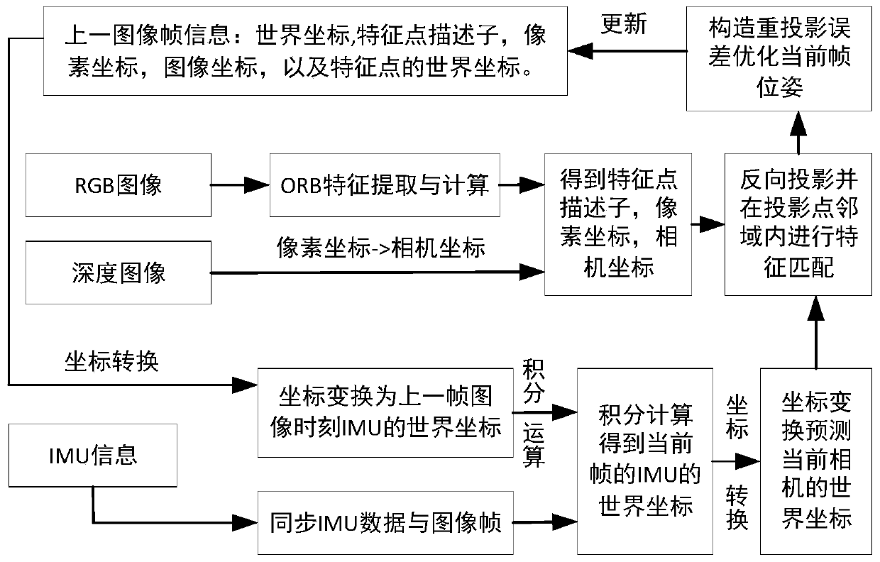
[0048] Such as figure 1 As shown, the present embodiment is based on the method for positioning a mobile robot fused with an RGB-D camera and an IMU, and the specific real-time steps are as follows:

[0049] Step (1): Establish a pinhole camera model.

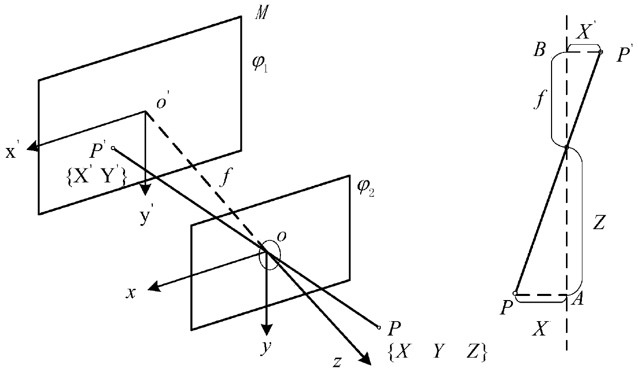
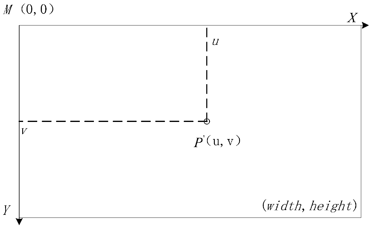
[0050] consider as figure 2 The pinhole camera model shown, where The plane is the imaging plane, The plane is the camera plane. Among them, xyz is the camera coordinate, the z axis in the camera coordinate is perpendicular to the camera plane, and the xy axis is parallel to the two borders of the camera and forms a right-handed coordinate system with the z axis. The plane coordinate system x'y' is parallel to the xy axis respectively. o is the optical center of the camera, o' is the intersection point of the straight line passing through the optical center parallel to the z-axis and the imaging plane α, oo' is the focal length, and its size is f. Assuming that the coordinates of a point P in the three-dimensional spac...


PUM


Abstract

The invention discloses a mobile robot positioning method based on RGB-D camera and IMU information fusion. The method comprises the following steps: (1) establishing a pinhole camera model; (2) establishing an IMU measurement model; (3) performing structured light camera depth calculation and pose transformation calculation based on feature point matching; (4) carrying out IMU pre-integration attitude calculation and conversion between an IMU coordinate system and a camera coordinate system; and (5) performing an RGB-D data and IMU data fusion process and a camera pose optimization process, and finally obtaining an accurate positioning pose. According to the invention, the RGB-D camera and the IMU sensor are combined for positioning; the characteristic that the IMU has good state estimation in short-time rapid movement is well utilized, and the camera has the characteristic that the camera basically does not drift under the static condition, so that the positioning system has good static characteristics and dynamic characteristics, and the robot can adapt to low-speed movement occasions and high-speed movement occasions.

Description

technical field [0001] The invention belongs to the field of intelligent mobile robot perception, and in particular relates to a positioning method based on RGB-D camera and IMU information fusion. Background technique [0002] In recent decades, with the continuous advancement of science and technology, the degree of automation and intelligence in production and life has been continuously improved. Because of its ability to independently complete a certain task, mobile robots will inevitably play a huge role in human production and life in the future. . For example, space exploration, ocean exploration, industrial mine exploration and other tasks that are very dangerous or even impossible for humans to complete, with the participation of robots, it will be better, faster and safer to complete these dangerous tasks. The autonomous movement of an intelligent mobile robot needs to continuously obtain its own position and posture information to provide corresponding positionin...

Claims


Application Information

Patent Timeline
IPC IPC(8): G01C21/18G01C21/16G01C11/00G01C9/00
CPCG01C21/18G01C21/165G01C9/00G01C11/00
Inventor 戴诗陆欧建永杨辰光王柠
Owner SOUTH CHINA UNIV OF TECH
Learn More