Floor structure and combined structure residential system with same

A floor and floor slab technology, which is applied to floors, building components, building structures, etc., can solve the problems of low production efficiency of four-sided ribs and complex construction of integral joints, so as to facilitate factory automated mass production and high construction efficiency , the effect of reducing the amount of concrete

Pending Publication Date: 2020-05-19
SHENZHEN YJY BUILDING TECH +2
View PDF0 Cites 1 Cited by
  • Summary
  • Abstract
  • Description
  • Claims
  • Application Information

AI Technical Summary

Problems solved by technology

[0005] The purpose of the present invention is to provide a floor structure and its composite structure housing system to solve the technical problems in the prior art of low production efficiency of four-sided reinforcement and complex on-site construction of integral joints

Method used


Image

  • Floor structure and combined structure residential system with same
  • Floor structure and combined structure residential system with same
  • Floor structure and combined structure residential system with same

Examples


Embodiment 1

[0097] The floor structure provided in this embodiment includes: a floor slab and a pick-up plate; in a horizontal projection plane, the floor slab is arranged indoors, and the pick-up plate is arranged outdoors.

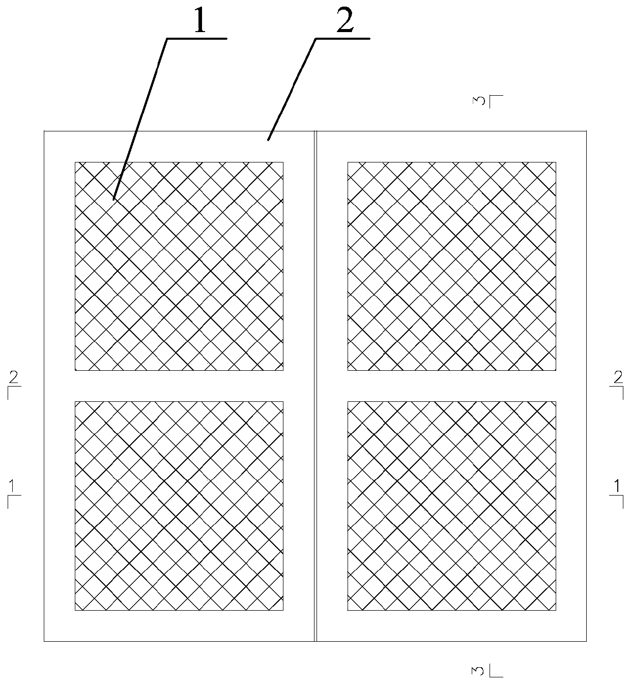
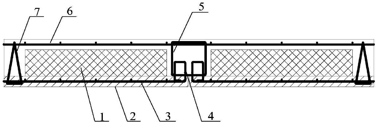
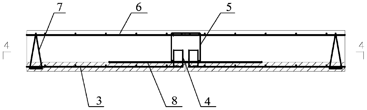
[0098] Such as Figure 1-Figure 7 As shown, it includes a reinforcement skeleton and two floor slabs arranged at intervals; one end of the floor slab located at the splicing surface is provided with an installation gap; the bottom of the installation gap is vertically fixed with floor ring bars 4 at intervals along the length direction of the floor splicing surface; The skeleton includes connecting horizontal ribs 9 arranged along the length direction of the splicing surface and a plurality of connecting ring ribs 5 fixed to the connecting horizontal ribs 9; the connecting ring ribs 5 are parallel to the floor ring ribs 4; A plurality of floor slab ring bars 4 are arranged in a staggered manner; the connecting ring bars 5 and the floor slab ring bars 4 are poured wi...

Embodiment 2

[0151] This embodiment discloses a combined structure housing system. This embodiment is basically the same as Embodiment 2, except that:

[0152] Such as Figure 25 As shown, the combined structure residential system includes a restraint support 60; the two ends of the restraint support 60 are fixedly connected to the middle part of the column and the middle part of the steel beam respectively.

[0153] Such as Figure 26 As shown, the constraining support 60 includes an outer constraining sleeve 61 and an inner core 62 , a constraining ring 63 and a constraining rod 64 all disposed in the outer constraining sleeve.

[0154] The restraint rod 64 and the inner core 62 are all arranged along the length direction of the outer restraint sleeve, and the restraint ring 63 is fixed to the outer restraint sleeve, and is sleeved outside the inner core 62 and the restraint rod 64 to fix the inner core 62 and the restraint rod 64 .

[0155] As shown in 26, the inner core 62 is in the...

Embodiment 3

[0161] This embodiment discloses a combined structure housing system, which is basically the same as Embodiment 2, the difference lies in:

[0162] Such as Figure 29-Figure 32 As shown, a column 30 provided in this embodiment includes a round steel pipe 31 and 2-4 T-shaped steels 32; the round steel pipe 31 is poured with concrete 33, and a plurality of T-shaped steels 32 are spaced along the circumferential direction of the round steel pipe 31. Set, and the opposite end of the T-shaped steel 32 web and the flange is fixedly connected to the outer wall of the round steel pipe 31; the web 32b of the T-shaped steel 32 is located on the extension line of the diameter of the round steel pipe 31, and the flange 32a is provided with bolt holes.

[0163] Among them, several T-shaped steel 32 are arranged in various ways, such as Figure 29 As shown, there are two T-shaped steels 32, and the webs of the two T-shaped steels 32 are located on the same diameter of the round steel pipe ...


PUM


Abstract

The invention relates to a floor structure and a combined structure residential system with the same. The floor structure comprises floor slabs and cantilever slabs; a steel reinforcement framework isarranged in the space between every two adjacent floor slabs; floor ring ribs are sequentially and vertically fixed at intervals along the length direction of the floor slab splicing surface at the bottom of an installation notch; each steel reinforcement framework comprises a connecting horizontal rib arranged along the length direction of the splicing surface and a plurality of connecting ringribs fixed to the connecting horizontal rib; the connecting ring ribs are parallel to the floor ring ribs; concrete is poured into the connecting ring rib sand the floor ring ribs; and the floor slabsand the cantilever slabs are connected through cold-hot-proof bridge nodes. According to the structure, the on-site construction speed is greatly improved, the construction difficulty is reduced, theconstruction process is simple, the four sides of a prefabricated plate are free of reinforcement rib exposing, the automatic batch production of factories is facilitated, and the production cost isgreatly reduced; the stress performance is good, the integrity is strong, and the structural integrity in the assembly integral mode is strong; and on-site assembly construction is realized, the construction efficiency is high, the self weight and the concrete consumption of a floor are greatly reduced by the multi-rib structure, and the cost is reduced.

Description

technical field [0001] The invention relates to the technical field of buildings, in particular to a floor structure and a combined structure housing system. Background technique [0002] The cast-in-place floor slab has the advantages of good structural integrity and good seismic performance, but it is labor-intensive and requires a large number of formwork, the construction period is long, and it is difficult to realize industrial production. Prefabricated floor slabs are easy to realize the industrialization of building components. The production of components is not limited by seasons and climates, which can improve the quality of components, and the construction speed is fast, which can save a lot of formwork and supports, but the integrity is poor, which is not conducive to earthquake resistance and poor impermeability. Laminated slabs can combine the advantages of cast-in-place slabs and prefabricated slabs, and have the advantages of fast construction speed, short co...

Claims


Application Information

Patent Timeline
Patent Type & Authority Applications(China)
IPC IPC(8): E04B1/00E04B5/00E04B1/76
CPCE04B1/00E04B1/76E04B5/00Y02A30/244
Inventor 龚超王罡李庆伟刘晓刚廉旭
Owner SHENZHEN YJY BUILDING TECH
Why Eureka
Try Eureka