Material surface treatment device
A surface treatment device and treatment chamber technology, which is applied to discharge tubes, electrical components, circuits, etc., can solve the problems of low work efficiency and long processing time by laser method, and achieve small overall temperature rise, small deformation, and good surface finish. Effect
- Summary
- Abstract
- Description
- Claims
- Application Information
AI Technical Summary
Problems solved by technology
Method used
Image
Examples
Embodiment 1
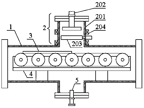
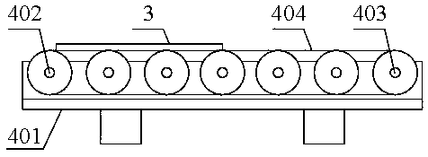
[0036] like Figure 1 to Figure 3 As shown, the material surface treatment device includes a treatment chamber 1 , an electron gun 2 installed inside the treatment chamber 1 , an operating table 3 and an adjustment mechanism 4 , and an exhaust hole 5 is provided on one side of the treatment chamber 1 . In the figure, the processing chamber 1 is a sealed chamber structure with covers at both ends, and the electron gun 2 is vertically arranged directly above the processing chamber 1. The electron gun 2 is composed of a gun barrel 201, a cathode 202 for emitting electron beams, and a An anode 203 for beam transmission and a solenoid 204 for collecting electron beams are composed. One end of the gun barrel 201 communicates with the inside of the processing chamber 1, and the other end of the gun barrel 201 is equipped with a cathode 202. The anode 203 is a ring or hollow column structure And it is arranged directly below the cathode 202 , and the solenoid 204 is coiled on the oute...
Embodiment 2
[0045] On the basis of embodiment one, an electrospray gun 6 is added, and the electrospray gun 6 can be used for surface alloy forming of the processed material, such as Figure 4 As shown, the electrospray gun 6 and the electron gun 2 are arranged side by side on the processing chamber 1. Specifically, the electrospray gun 6 is composed of a nozzle 601, a plasma generator 602 for generating electrons, and an electroplating object 603 for generating electroplating ions. , wherein: one end of the nozzle 601 communicates with the inside of the processing chamber 1 , the other end of the nozzle 601 is installed with a plasma generator 602 , and the electroplating object 603 is arranged directly below the plasma generator 602 .
[0046] Specifically, the plasma generating electrode 602 is connected to the positive electrode, and the electroplating object 603 is connected to the negative electrode. Generally, a voltage of 220V is used. In actual use, the output voltage of the power...
Embodiment 3
[0051] like Figure 5 to Figure 7 As shown, this embodiment includes a treatment chamber 1 and an electron gun 2 installed inside the treatment chamber 1, an operating table 3, an adjustment mechanism 4, and an electric spray gun 6. The side of the treatment chamber 1 is also provided with an exhaust hole 5, but the electron gun 2 and the layout scheme of the electrospray gun 6 are intersecting layout schemes. In the figure, the electron gun 2 is in a horizontal position, the electrospray gun 6 is in a vertical position, and the treatment chamber 1 has adopted a cylindrical or circular cavity compared with embodiments one and two, which is more compact.
[0052] In the figure, the adjustment mechanism 4 adopts a rotation adjustment mechanism, which specifically includes a rotating table 405 and a rotating shaft 406. The rotating table 405 is a load-bearing body. The rotating table 405 is installed inside the processing chamber 1 through a rotating shaft 406. The rotating shaft...
PUM
 Abstract
Description
Claims
Application Information
 - R&D
- Intellectual Property
- Life Sciences
- Materials
- Tech Scout
- Unparalleled Data Quality
- Higher Quality Content
- 60% Fewer Hallucinations
Browse by: Latest US Patents, China's latest patents, Technical Efficacy Thesaurus, Application Domain, Technology Topic, Popular Technical Reports.
© 2025 PatSnap. All rights reserved.Legal|Privacy policy|Modern Slavery Act Transparency Statement|Sitemap|About US| Contact US: help@patsnap.com


