Roller type continuous cold roll forming method for U-shaped steel sheet pile

A cold-formed and steel sheet pile technology, applied in the field of sheet pile forming and processing, can solve the problems of sheet springback angle, high equipment cost and precision requirements, rough surface at the bend, etc., to avoid rigid contact and save roller frames. The effect of reducing the number of passes and reducing the wear of the roll die

Active Publication Date: 2020-05-22
南京图信新材料科技有限公司
View PDF6 Cites 2 Cited by
  • Summary
  • Abstract
  • Description
  • Claims
  • Application Information

AI Technical Summary

Problems solved by technology

[0004] The U-shaped steel sheet pile roll-type cold-bending forming process in the prior art has the following defects: (1) The locks on both sides of the U-shaped steel sheet pile are in an arc-shaped reverse bending structure, and the upward forming method is adopted according to the design concept of Eurogang. In addition to using upper and lower rollers, side vertical rollers are also needed to help shape, resulting in high equipment cost and high precision requirements; (2) The arc-shaped connection on the side of the lock has insufficient contact bearing capacity. Insufficient straight force and formability lead to large continuous twisting torque, complex process, high requirements on the forming surface of the roll, which affects the reliability of the lock connection; (3) The deformation angle of the bending pass is large, and it is easy to exceed the plate and the roll The yield strength limit of the wheel, especially for steel with high carbon or alloy content, will cause severe wear of the roller, rough surface at the bend, obtuse angle bending cracks or cracks, excessive thinning of the neutral layer at the bend, and plate back The elastic angle affects the degree of plastic deformation and material stiffness, making it difficult to meet the quality of finished products

Method used


Image

  • Roller type continuous cold roll forming method for U-shaped steel sheet pile
  • Roller type continuous cold roll forming method for U-shaped steel sheet pile
  • Roller type continuous cold roll forming method for U-shaped steel sheet pile

Examples


Embodiment Construction

[0038] The specific embodiments of the present invention will be further described below in conjunction with the accompanying drawings.

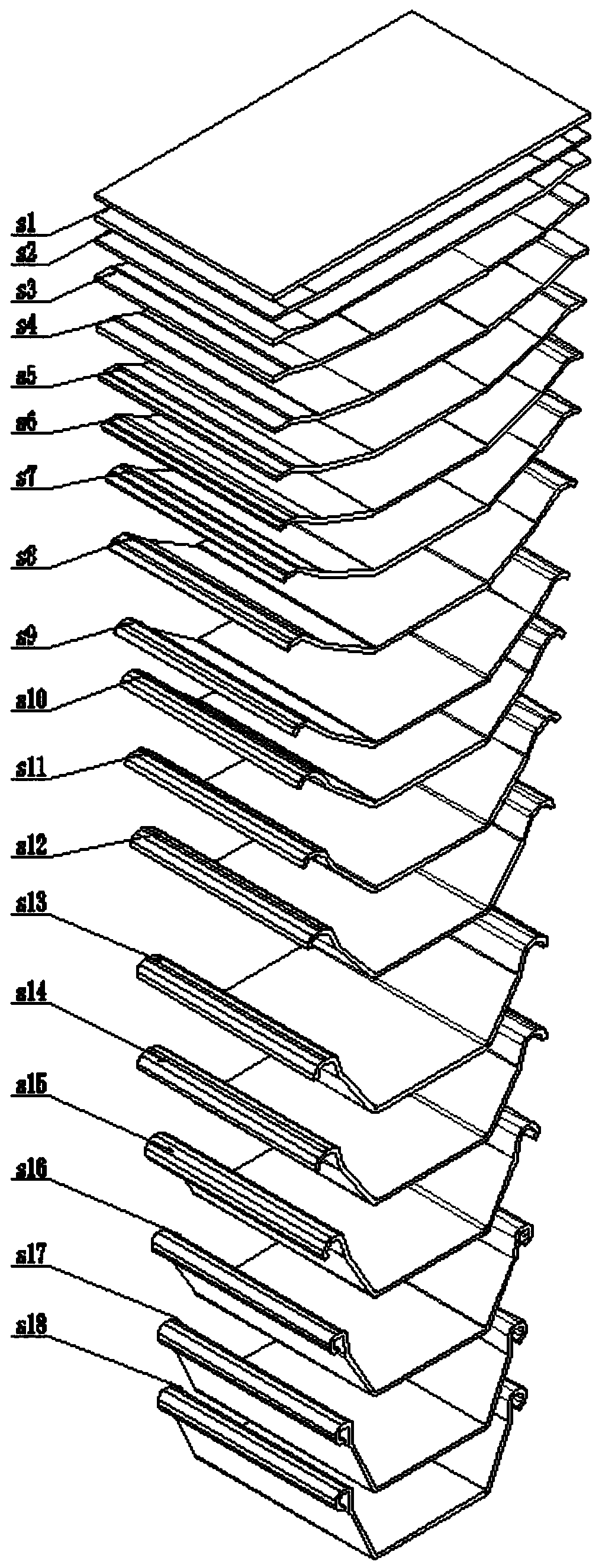
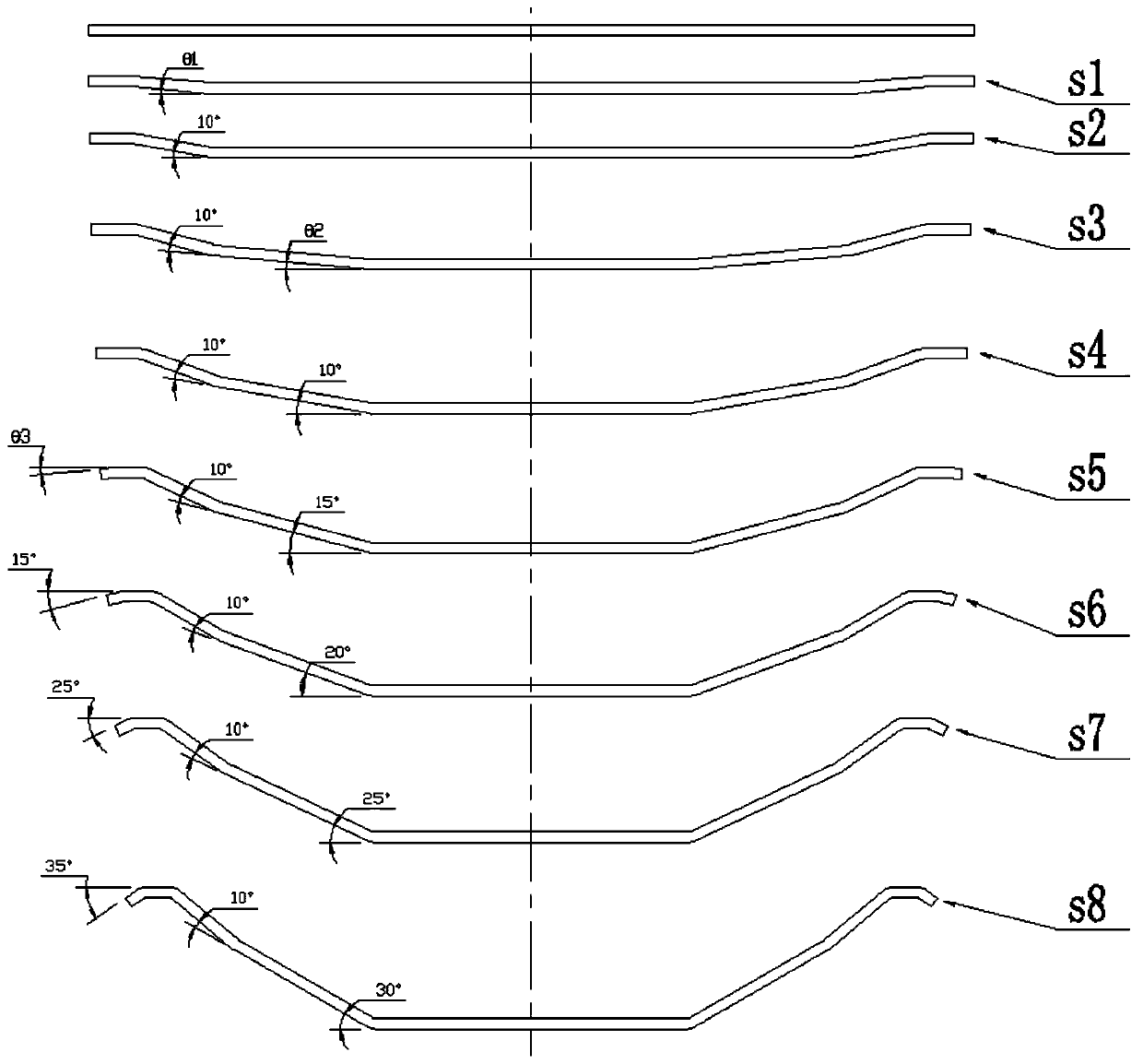
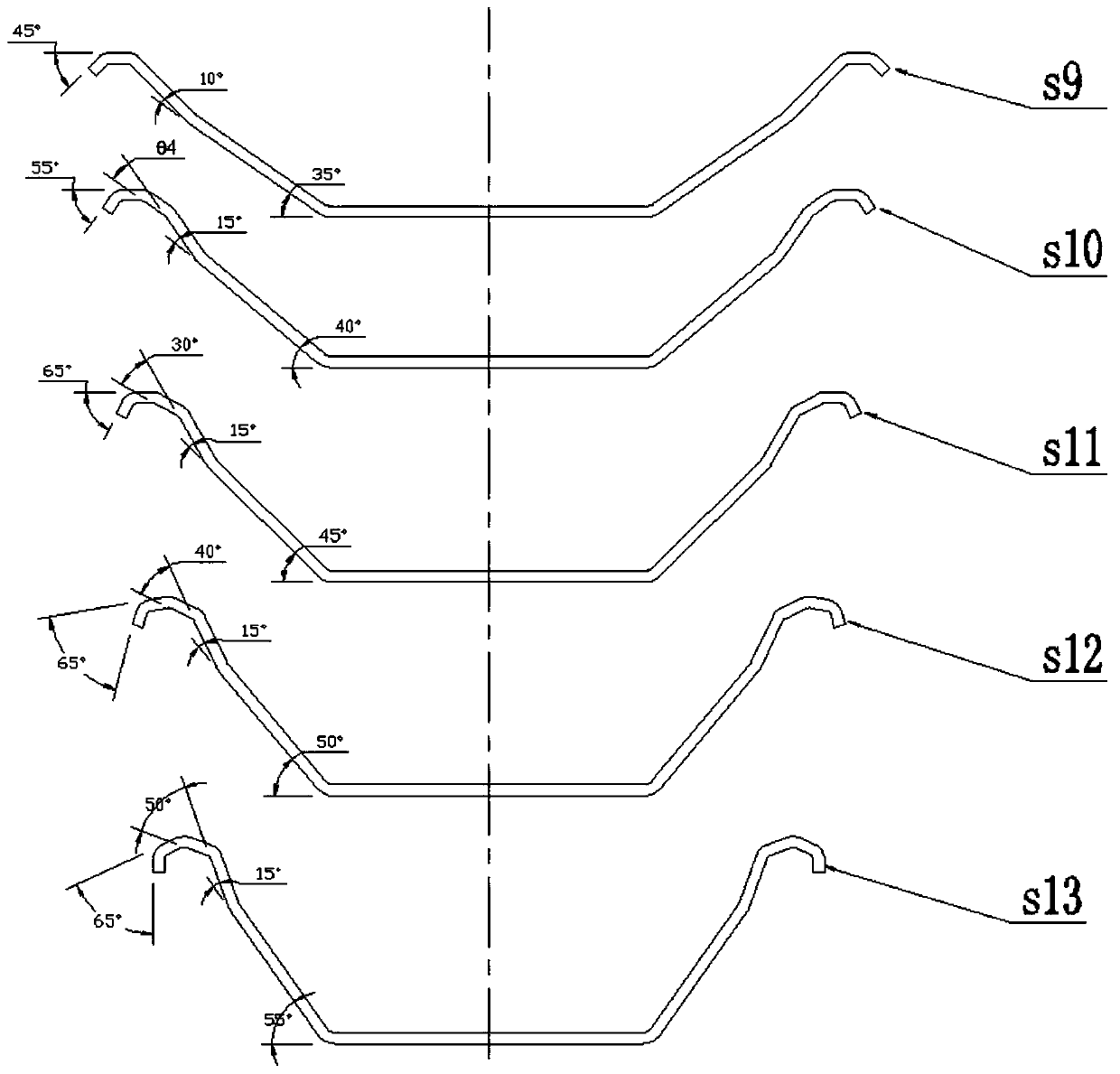
[0039] A roll-type continuous cold-bending forming method for U-shaped steel sheet piles, wherein the forming method is as follows:

[0040] S1: Straighten the strip just after passing through the decoiler, place the flattened strip on the roller cold bending forming machine, and enter the first symmetrical upper and lower paired roller mold, so that the two sides of the steel strip are bent symmetrically to the horizontal line The shape of θ1, θ1 is less than or equal to 5°;

[0041] S2: The strip just advances smoothly into the second pair of symmetrical roller molds, so that the strip passes through the first symmetrical bend on both sides of step S1, and forms a shape with an incremental angle of 5° with the horizontal line;

[0042] S3: The strip just moves forward and smoothly enters the third pair of symmetrical roller molds, so that...


PUM


Abstract

The invention relates to a roller type continuous cold roll forming method for a U-shaped steel sheet pile. The forming method of the U-shaped steel sheet pile comprises the following steps that stripsteel is placed on a rolling cold roll forming machine, and the strip steel advances and smoothly and continuously enters symmetric up-and-down paired roller dies from a first frame to a seventeenthframe, so that the two sides of the strip steel are bent symmetrically to be provided with a first bending part, a second bending part, a third bending part and a fourth bending part in sequence, specifically, the outer side of the first bending part is vertical, the second bending part is in the shape of an increment angle theta 5 from the horizontal plane, and the inner side of the third bendingpart is vertical; and a U-shaped steel sheet pile is hinged flat and shaped, and then is fed into a cutting unit for fixed-length cutting to obtain a U-shaped steel sheet pile finished product. Through the above method, a U-shaped main body and two-side lock catch structures of the U-shaped steel sheet pile are synchronously formed, the adjacent U-shaped steel sheet pile lock catches are in a straight bearing surface mode through continuous cold roll, the torque of an upward forming method of the lock catches is reduced, the pass of the roller frames is saved, the connection bearing performance and the connection reliability of the adjacent U-shaped steel sheet piles are improved favorably, the loss of the roller dies is reduced, and bending cracks are avoided, so that the U-shaped steelsheet pile meets the use requirements better.

Description

technical field [0001] The invention relates to a roll-type continuous cold-bending forming method for U-shaped steel sheet piles, and belongs to the technical field of steel sheet pile forming processing. Background technique [0002] U-shaped steel sheet pile is a type of steel with locks on both sides and the shape of the letter U as a whole. It has good water-tightness, is conducive to earthquake-resistant design, can be reused, and is conducive to earthquake-resistant design. It can be connected with each other through locks. The steel sheet piles are driven or pressed into the foundation with a pile driver, so that they are connected to each other to form a steel sheet pile wall, which is used to retain soil and water and is widely used in bank revetment engineering, mining engineering, and building foundation engineering. According to the production process, it can be divided into thermal Rolled tensile steel sheet piles and cold-formed steel sheet piles, among which ...

Claims


Application Information

Patent Timeline
IPC IPC(8): B21D31/00
CPCB21D31/005
Inventor 孙发明张顺生
Owner 南京图信新材料科技有限公司
Why Eureka
Try Eureka