Iron furnace slag and coal cinder ash autoclaved brick production device

A production device, cinder ash technology, applied in the direction of supply device, unloading device, auxiliary molding equipment, etc., can solve the problems of easy solidification of raw materials in the storage tank, reduce work efficiency, inconvenient use, etc., to improve quality and appearance , high work efficiency, and the effect of improving quality

Active Publication Date: 2020-06-02
淮北市恒兴新型建材科技有限公司
View PDF2 Cites 6 Cited by
  • Summary
  • Abstract
  • Description
  • Claims
  • Application Information

AI Technical Summary

Problems solved by technology

[0006] The purpose of the present invention is to provide a production device for iron slag and cinder ash autoclaved bricks, to solve the problem that the autoclaved bricks in the above background technology need to transport the prepared mixed raw materials to the forming mold during the production process, and the mixed raw materials It is usually stored in the storage tank, but due to the long feeding process, the raw materials in the storage tank will be easily solidified, the fluidity is poor, and it will be difficult to unload the material. Moreover, the current unloading switch needs manual operation, which is very inconvenient to use. , reduce work efficiency, after the autoclaved brick processing is completed, the product needs to be taken out of the molding cavity, and now it is usually to reverse the mold and then let the product fall, which is a troublesome operation

Method used


Image

  • Iron furnace slag and coal cinder ash autoclaved brick production device
  • Iron furnace slag and coal cinder ash autoclaved brick production device
  • Iron furnace slag and coal cinder ash autoclaved brick production device

Examples


Embodiment Construction

[0044] The following will clearly and completely describe the technical solutions in the embodiments of the present invention with reference to the accompanying drawings in the embodiments of the present invention. Obviously, the described embodiments are only some, not all, embodiments of the present invention. The specific embodiments described here are only used to explain the present invention, not to limit the present invention. Based on the embodiments of the present invention, all other embodiments obtained by persons of ordinary skill in the art without making creative efforts belong to the protection scope of the present invention.

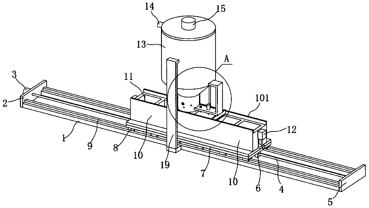
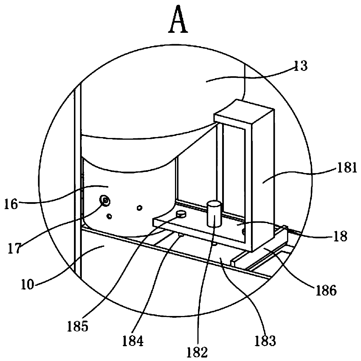
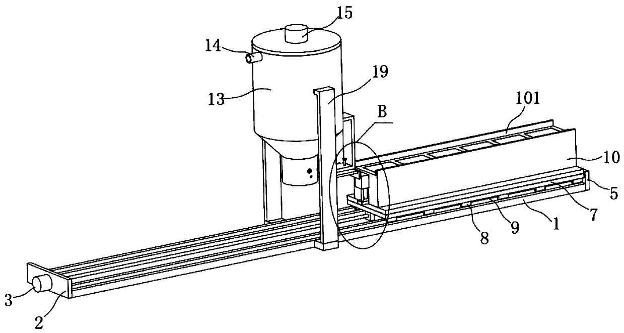
[0045] The present invention provides such Figure 1-13 A production device for iron slag and cinder ash autoclaved bricks shown, comprising a mounting base 1, one end of the mounting base 1 is fixed with a first mounting plate 2, and the first mounting plate 2 is fixed with bolts The first servo motor 3, the end of the output shaft of t...


PUM


Abstract

The invention discloses an iron furnace slag and coal cinder ash autoclaved brick production device. The iron furnace slag and coal cinder ash autoclaved brick production device comprises a mounting seat, wherein a first mounting plate is fixed at one end of the mounting seat; a first servo motor is fixed on the first mounting plate; a screw rod is fixed on an output shaft of the first servo motor; the screw rod is in threaded connection with a movable block; a movable seat is welded to the movable block; a forming die is mounted on the movable seat; a plurality of forming cavities are formedin the forming die; a material ejection mechanism is arranged in each forming cavity; a material storage barrel is arranged in the middle of the mounting seat; the material storage barrel is welded tothe mounting seat through a supporting frame; the upper end of the material storage barrel communicates with a feeding pipe; a stirring mechanism is arranged in the material storage barrel; the bottom end of the material storage barrel communicates with a discharging pipe; a discharging switch mechanism is arranged in the discharging pipe; a material pressing mechanism is arranged on one side ofthe lower end of the discharging pipe; and the forming die is located below the discharging pipe and the material pressing mechanism. By adopting the iron furnace slag and coal cinder ash autoclaved brick production device, raw materials are stirred and the flowability is improved; and automatic discharging, material pressing, material scraping and material ejection are realized, and the working efficiency is high.

Description

technical field [0001] The invention belongs to the technical field of autoclaved brick production devices, and in particular relates to a production device for iron slag and cinder ash autoclaved bricks. Background technique [0002] Autoclaved fly ash brick refers to fly ash, lime or cement as the main raw material, mixed with appropriate amount of gypsum and aggregate, prepared by mixture, blank material preparation, compression molding, high-pressure steam curing, referred to as fly ash brick. There are two types of fly ash bricks: non-autoclaved fly ash bricks and steam-cured fly ash bricks. Autoclaved fly ash bricks refer to fly ash bricks made by high pressure steam curing. Steam-cured fly ash bricks refer to fly ash bricks made by steam curing under normal pressure. [0003] In the production process of autoclaved bricks, the prepared mixed raw materials need to be transported to the forming mold. The mixed raw materials are usually stored in the storage tank. How...

Claims


Application Information

Patent Timeline
Patent Type & Authority Applications(China)
IPC IPC(8): B28B5/04B28B13/02B28B1/29B28B17/00B28B13/06
CPCB28B1/29B28B5/04B28B13/0235B28B13/065B28B17/00
Inventor 孙蓉
Owner 淮北市恒兴新型建材科技有限公司
Why Eureka
Try Eureka