
Dry compartment heat preservation system utilizing LNG ship engine room hot air

A technology of hot air and compartment, applied in some cabins in the hull, hull ventilation/heating/cooling, hull and other directions, can solve the problems of inability to use directly, too much heat dissipation, waste of heat energy, etc., and achieve great practical application value and save energy. , the effect of improving the economy

Pending Publication Date: 2020-06-05
QINGDAO UNIV OF SCI & TECH
View PDF10 Cites 4 Cited by
  • Summary
  • Abstract
  • Description
  • Claims
  • Application Information

AI Technical Summary

Problems solved by technology

Most of the space in the engine room is located under the deck of the ship, and the engine room is a relatively airtight space. In addition, the power of the main engine, auxiliary engine, boiler and other large equipment in the engine room is relatively large, which can reach about 30,000KW. The equipment dissipates heat during operation. Therefore, the air temperature in the engine room is very high, but the operation and management of the equipment in the ship’s engine room requires on-site control by personnel, so that the temperature of the engine room cannot be too high. On ships, fans are generally used to deliver cold air from nature to the engine room. Even so, the ship’s engine room The temperature in winter can reach at least 30°C to 40°C, and the temperature in the cabin in summer is even around 40°C to 60°C.
Therefore, there is hot air with a higher temperature in the engine room of the ship, but this low-grade waste heat generally cannot be directly used, and usually the hot air is directly discharged into nature, which causes a waste of heat energy

Method used


Image

  • Dry compartment heat preservation system utilizing LNG ship engine room hot air
  • Dry compartment heat preservation system utilizing LNG ship engine room hot air
  • Dry compartment heat preservation system utilizing LNG ship engine room hot air

Examples


Embodiment Construction

[0023] In order to make the object, technical solution and advantages of the present invention clearer, the present invention will be further described in detail below in conjunction with the accompanying drawings and embodiments.

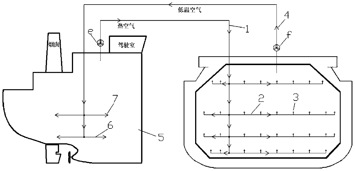
[0024] Such as figure 1 , is a schematic diagram of the piping system of the engine room of the present invention and any dry compartment. This dry compartment thermal insulation system utilizing the hot air in the engine room of an LNG ship mainly includes a dry compartment part and an engine room part. Wherein, the dry compartment part mainly includes: hot air blower (e), hot air duct (1), dry compartment air supply branch pipe (2), dry compartment branch pipe outlet (3); the engine room part mainly includes : air cooler (f), low-temperature air duct (4), engine room (5), engine room air supply duct (6), engine room air supply duct outlet (7).

[0025] Wherein, the inlet of the hot air pipeline (1) is at the uppermost part in the engine room (5...


PUM


Abstract

The invention discloses a dry compartment heat preservation system utilizing LNG ship engine room hot air. The system mainly comprises a dry compartment part and an engine room part. Hot air from theengine room enters the dry compartment through the air heater and the pipeline, releases heat, becomes low-temperature air, then returns to the engine room of the ship through the air cooler and the pipeline, absorbs the heat in the engine room and becomes hot air, and thus a cycle is formed. On the premise that no extra heat source is consumed in the dry compartment, it can be guaranteed that thedry compartment can meet the temperature requirement specified by relevant specifications of the ship, the low-grade heat source in the air of the marine engine room can be utilized, the energy utilization rate of the ship can be increased, and in addition, the temperature in the engine room can be reduced. The design method is simple, convenient to operate and high in economical efficiency, andhas great practical application value.

Description

technical field [0001] The invention belongs to the technical field of ships, and relates to a dry compartment insulation system utilizing hot air in an engine room of an LNG ship. Background technique [0002] Liquefied Natural Gas (Liquefied Natural Gas) carrier, referred to as "LNG carrier", refers to a ship dedicated to transporting liquefied natural gas. At present, most of the cargo holds of LNG ships in the world use a membrane-type containment system. In order to increase the ship’s sinking resistance and damage stability, multiple cargo holds are generally set up on this type of ship. There is also a cofferdam between them, which is a narrow space with only one rib spacing, usually called a dry compartment. This kind of LNG ship is usually equipped with 4 liquid cargo tanks and 5 dry compartments, and ship ballast tanks are set on the left and right sides of the cargo tanks. Through the arrangement of such tanks, it is ensured that there is a complete double-hull h...

Claims


Application Information

Patent Timeline
Patent Type & Authority Applications(China)
IPC IPC(8): B63J2/12B63B11/00
CPCB63J2/12B63B11/00Y02T70/00
Inventor 李博洋杨倩倩邓芳王龙金李保军姚文龙马钰强
Owner QINGDAO UNIV OF SCI & TECH
Learn More