Prefabricated composite member and production method thereof, and prefabricated composite wall and construction method thereof

A technology of stacking components and walls, which is used in building components, walls, building structures, etc.

Active Publication Date: 2020-06-05
SHANGHAI JOHNSON ARCHITECTURAL & ENG DESIGN CONSULTANTS
View PDF10 Cites 2 Cited by
  • Summary
  • Abstract
  • Description
  • Claims
  • Application Information

AI Technical Summary

Problems solved by technology

[0005] The purpose of the present invention is to provide a prefabricated laminated component and its production method as well as a prefabricated laminated wall and its construction method...

Method used


Image

  • Prefabricated composite member and production method thereof, and prefabricated composite wall and construction method thereof
  • Prefabricated composite member and production method thereof, and prefabricated composite wall and construction method thereof
  • Prefabricated composite member and production method thereof, and prefabricated composite wall and construction method thereof

Examples


Embodiment 1

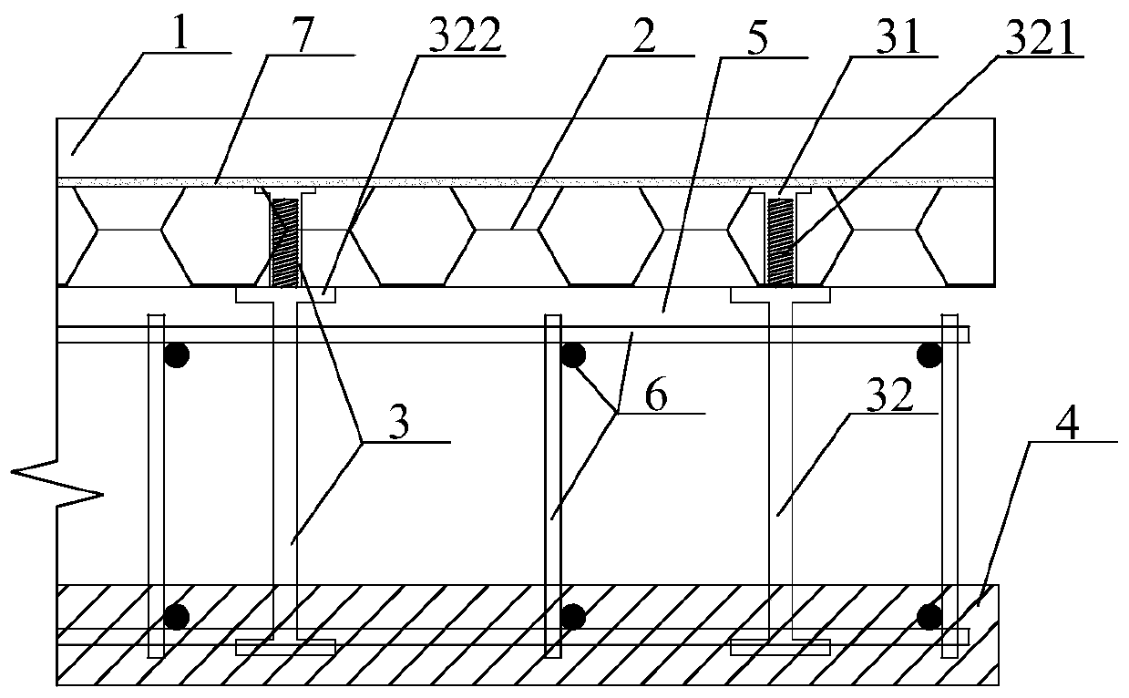
[0110] This embodiment provides a prefabricated laminated component, such as figure 1 , 2 ,include:

[0111] The veneer 1 and the insulation board 2 are connected to each other. The veneer 1 is preferably made of lightweight materials such as foamed ceramics; the veneer is a finished hard veneer with a fire rating of A1, which itself has good thermal insulation performance and high strength, and can further improve the thermal insulation effect after being integrated with the thermal insulation board. The insulation board 2 is preferably a grade A insulation board. There are many specific connection methods, figure 1 Shown in 7 are connected by bonding mortar. Use other adhesive, bolted joints, special joints ( image 3 display) and other connections are available. The reinforcement cage 6 connected with the inner leaf plate 4. The inner blade 4 can be made of concrete, and the connection with the reinforcement cage 6 can be directly fixing the reinforcement cage 6 in t...

Embodiment 2

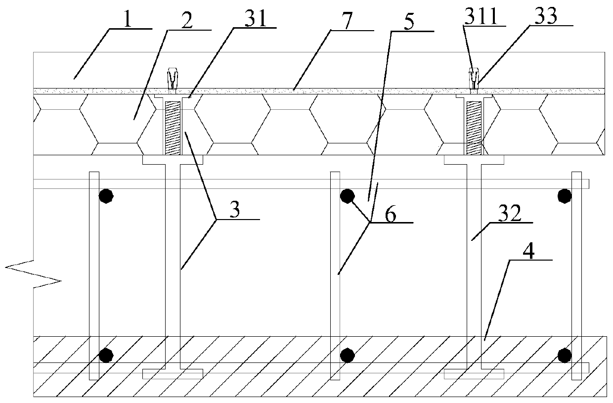
[0120] Such as figure 2 , the present embodiment provides another prefabricated laminated component, the veneer 1 and the insulation board 2 connected to each other; the reinforcement cage 6 connected with the inner blade 4; the cavity 5 is formed between the insulation board 2 and the inner blade 4; A plurality of connection components 3 for interconnecting the insulation board 2 and the inner blade board 4 .

[0121] This embodiment and figure 1 The difference in the specific structure shown is that the connection assembly 3 also includes an expansion tube 33 embedded in the veneer 1, and an overhanging piece 311 arranged at one end of the built-in component 31, and the overhanging piece 311 extends into the expansion tube 33 and expands the expansion. The diameter of the pipe 33 is to connect the veneer 1 and the insulation board 2. The combination of the overhanging part 311 and the expansion tube 33 can not rely on the adhesive mortar 7 or the claw connector 8 ( imag...

Embodiment 3

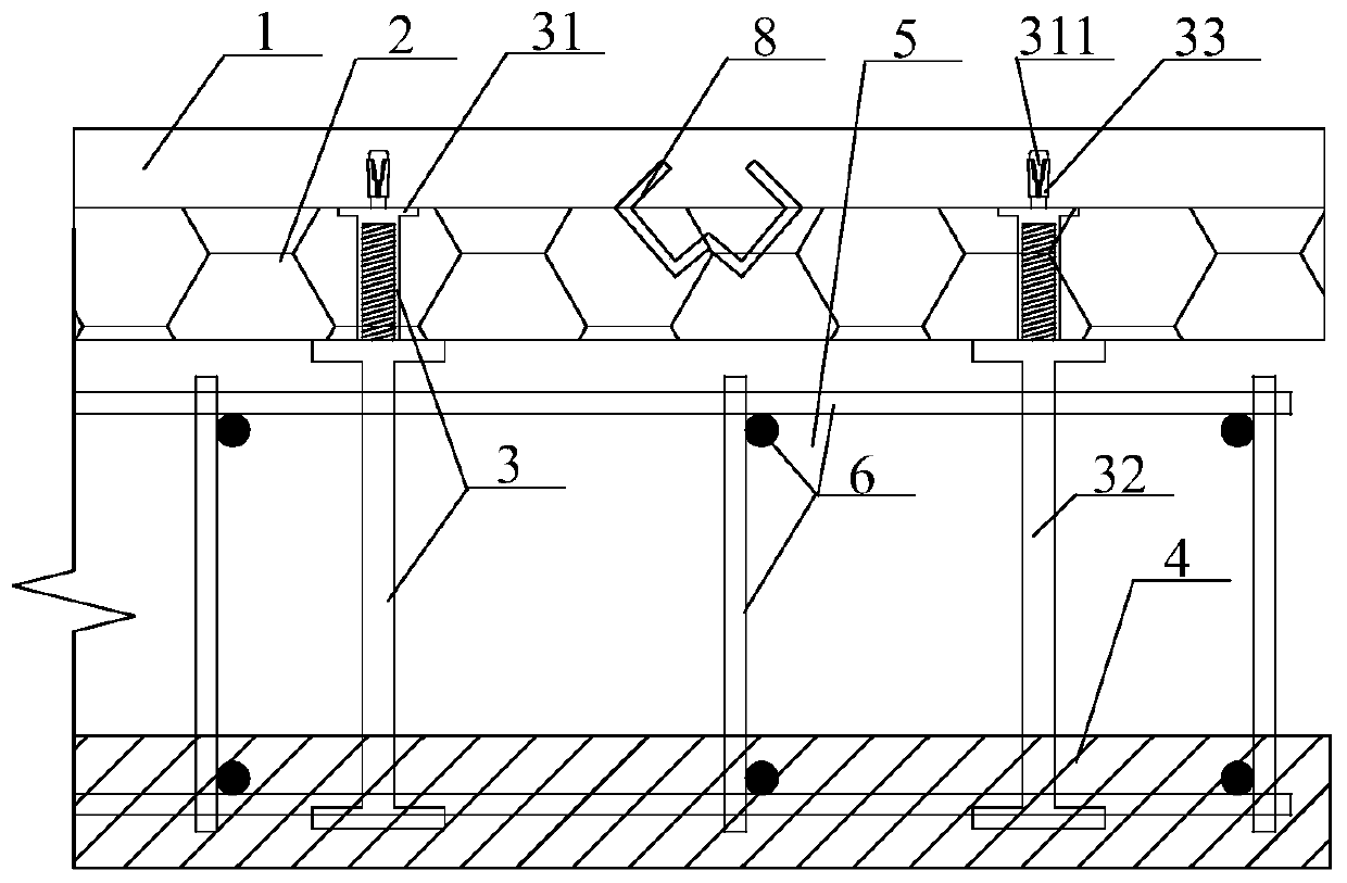
[0128] Such as image 3 , the present embodiment provides yet another prefabricated composite member, the veneer 1 and the insulation board 2 connected to each other; the reinforcement cage 6 connected with the inner blade 4; the cavity 5 is formed between the insulation board 2 and the inner blade 4; A plurality of connection components 3 for interconnecting the insulation board 2 and the inner blade board 4 .

[0129] Compared with embodiment one, this embodiment and figure 1 The difference in the specific structure shown is that the veneer 1 and the insulation board 2 are connected by several claw-shaped connectors 8 . If it is a finished insulation board 2, it is more suitable for bonding mortar 7 to connect; if the insulation board 2 is poured with slurry, it is more suitable for claw-shaped connectors 8 to connect. After the claw-shaped connector 8 is first connected to the veneer 1, the slurry is directly poured on the veneer 1 with the claw-shaped connector 8 to form...


PUM


Abstract

The invention belongs to the field of building outer walls, and discloses a prefabricated composite member and a production method thereof, and a prefabricated composite wall and a construction methodthereof. The prefabricated composite member comprises a veneer and an insulation board which are connected with each other, a reinforcement cage connected with an inner board, and a plurality of connecting assemblies used for mutually connecting the insulation board and the inner board, wherein a cavity is formed between the insulation board and the inner board, and the reinforcement cage is partially located in the cavity; each connecting assembly comprises a built-in component arranged in the insulation board and an assembly component connected with the built-in component; each assembly component is partially arranged in the inner plate and partially located in the cavity; and each assembly component further comprises a first connecting section connected with the built-in component andan inner side limiting piece connected with the first connecting section, wherein each inner side limiting piece is located in the cavity and abuts against the insulation board, and the diameter of each inner side limiting piece is larger than the diameters of the parts connected with the two sides of the inner side limiting piece. According to the scheme, the problem of heat preservation and exterior facing integration of a double-faced composite outer wall is solved, and the production and construction process is simple and efficient.

Description

technical field [0001] The invention belongs to the technical field of building walls, and in particular relates to a prefabricated laminated component integrating decorative panels and thermal insulation boards and a production method thereof, as well as a prefabricated laminated wall and a construction method thereof. Background technique [0002] The double-sided laminated shear wall combines the advantages of fast construction progress of the prefabricated structure and good integrity of the cast-in-place structure. The prefabricated part not only replaces the formwork of the cast-in-place part on a large scale, but also provides a certain structural strength for the shear wall structure, provides an operating platform for the structural construction, and reduces the pressure on the support system. At the same time, the laminated components do not need ribs, no grouting sleeves, high mold reuse rate, simple production process, effectively reducing costs and improving pro...

Claims


Application Information

Patent Timeline
IPC IPC(8): E04B2/86E04B1/76E04B1/68
CPCE04B2/86E04B1/76E04B1/6806
Inventor 马思遥赵辉李新华王伟薛霄
Owner SHANGHAI JOHNSON ARCHITECTURAL & ENG DESIGN CONSULTANTS
Why Eureka
Try Eureka