Magnetic imaging device and imaging method based on diamond NV color center and Kerr effect

A technology of Kerr effect and diamond, which is applied in measuring devices, the magnitude/direction of magnetic field, and magnetic performance measurement, etc., can solve the problems of limited imaging resolution, optical diffraction, inability to realize two imaging technologies, long-term and other problems, and achieve Meet the effect of high spatial resolution and large field of view global imaging

Pending Publication Date: 2020-06-05
致真精密仪器(青岛)有限公司
View PDF0 Cites 15 Cited by
  • Summary
  • Abstract
  • Description
  • Claims
  • Application Information

AI Technical Summary

Problems solved by technology

Not only can it not achieve synchronous global imaging, but it also takes a long time to scan a large area of ​​the sample surface; magneto-optical Kerr imaging can achieve global time-synchronous imaging, and the imaging field of view is wide, which can reach hundreds of microns to several millimeters
However, the imaging resolution is limited by optical diffraction, generally not better than 200nm
[0004] Since the optical path of the imaging system based on the diamond NV color center is a confocal optical path, which is different from the configuration, principle and operation method of the magneto-optical Kerr microscopic imaging system, it is impossible to compare the two imaging techniques on the same optical path in the traditional way. to implement

Method used


Image

  • Magnetic imaging device and imaging method based on diamond NV color center and Kerr effect
  • Magnetic imaging device and imaging method based on diamond NV color center and Kerr effect
  • Magnetic imaging device and imaging method based on diamond NV color center and Kerr effect

Examples


Embodiment Construction

[0064] In the following, the technical solutions described in the claims and the summary of the invention will be further explained and described in detail in conjunction with the accompanying drawings.

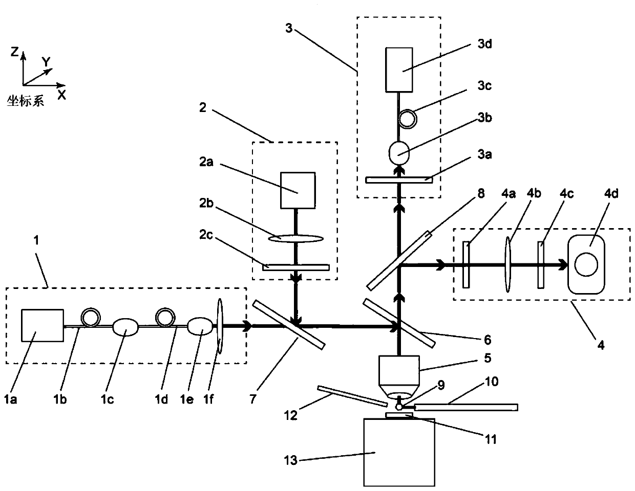
[0065] See attached figure 1 , the magnetic imaging device based on magneto-optical Kerr imaging and diamond nitrogen vacancy color center disclosed in this application, the device includes a spin control light source module 1, a polarized light generation module 2, a fluorescence detection module 3, a polarized light detection and imaging module 4 , Microscope objective lens 5, diamond probe 9 with NV color center, NV color center probe arm 10, microwave emitting device 12, displacement stage 13.

[0066] The spin control light source module 1 is used to provide a beam of incident laser light, through the dichroic mirror system, the laser light is transmitted and / or reflected by the dichroic mirror, and after the microscope objective lens 5 is focused, it irradiates the diam...


PUM

PropertyMeasurementUnit
wavelengthaaaaaaaaaa

Abstract

The invention discloses a magnetic imaging device and imaging method based on a diamond NV color center and a Kerr effect. A spinning control light source module provides a beam of incident laser, theincident laser passes through a dichroscope system and irradiates the NV color center of the diamond probe after being focused by the microscope objective lens, and fluorescence generated by the NV color center returns to the dichroscope system through the microscope objective lens and enters the fluorescence detection module. The polarized light generation module generates polarized light, the polarized light enters the microscope objective lens through transmission and/or reflection of the dichroscope system and then irradiates a sample placed on the displacement table, and after the polarized light is reflected by the sample, part of the polarized light enters the microscope objective lens again and then enters the polarized light detection and imaging module through the dichroscope system. Through the compatible design, high-resolution, global and large-view imaging of the sample is realized.

Description

Technical field: [0001] The invention belongs to the technical field of magnetic materials and magnetic field measurement, and in particular relates to a magnetic imaging device and method based on diamond NV color center and magneto-optical Kerr effect (also called Kerr effect in this application). It can be used for high spatial resolution and global magnetic imaging of materials, and has important application value in the fields of physics, materials, electronics and industrial detection. Background technique: [0002] The measurement of the magnetization state of magnetic materials is of great significance in physics, materials science, electronics and industrial production. In recent years, a magnetic measurement method using nitrogen-vacancy color centers (hereinafter referred to as NV color centers) in diamond has emerged. The principle is that the diamond with NV color center is used as the front end of the probe and placed near the sample to be tested. Under the a...

Claims


Application Information

Patent Timeline
Patent Type & Authority Applications(China)
IPC IPC(8): G01R33/032G01R33/12
CPCG01R33/032G01R33/0325G01R33/12
Inventor 张学莹王麟赵巍胜
Owner 致真精密仪器(青岛)有限公司
Why Eureka
Try Eureka