
Optical fiber gas pressure sensor and preparation method thereof

A gas pressure and sensor technology, which is applied in the application of optical methods for fluid pressure measurement, fluid pressure measurement, instruments, etc., can solve the problems of weak structural strength, difficult film preparation methods for plugging, temperature crosstalk, etc., and achieves low cost, High mechanical strength and high repeatability

Active Publication Date: 2020-06-12
HEILONGJIANG UNIV
View PDF14 Cites 7 Cited by
  • Summary
  • Abstract
  • Description
  • Claims
  • Application Information

AI Technical Summary

Problems solved by technology

[0004] In order to solve the problems that the existing FPI optical fiber gas sensor plugging film preparation method is difficult, the structural strength is weak, and the optical fiber itself and the plugging film material have thermo-optic coefficients and thermal expansion coefficients, and there is temperature crosstalk, the present invention provides a A kind of optical fiber gas pressure sensor and preparation method thereof

Method used


Image

  • Optical fiber gas pressure sensor and preparation method thereof
  • Optical fiber gas pressure sensor and preparation method thereof
  • Optical fiber gas pressure sensor and preparation method thereof

Examples


specific Embodiment approach 1

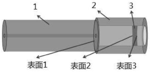
[0027] Specific implementation mode one: combine figure 1 Describe this embodiment, the fiber optic gas pressure sensor of this embodiment is an FPI fiber optic gas sensor;

[0028] The optical fiber gas pressure sensor is composed of a hollow-core optical fiber 2, a single-mode optical fiber 1 and a film 3, wherein one end 2 of the hollow-core optical fiber is welded to the single-mode optical fiber 1, and the other end of the hollow-core optical fiber is blocked with a film 3; Dimethylsiloxane film.

[0029] The optical fiber gas pressure sensor in this embodiment has three reflection surfaces, which are respectively named surface 1, surface 2 and surface 3. The three surface joint structures are divided into two FPI structures, one formed by surface 1 and surface 2, and the other formed by surface 1 and surface 3. However, the surface 3 in direct contact with the external environment is susceptible to fouling, resulting in roughening of the surface and reduction in reflec...

specific Embodiment approach 2

[0030] Embodiment 2: The difference between this embodiment and Embodiment 1 is that the thickness of the polydimethylsiloxane film is 1-71 μm. Other steps and parameters are the same as those in Embodiment 1.

[0031] The thickness of the polydimethylsiloxane film is the middle thickness of the film.

specific Embodiment approach 3

[0032] Embodiment 3: The difference between this embodiment and Embodiment 1 or 2 is that the thickness of the polydimethylsiloxane film is 3 μm. Others are the same as in the first or second embodiment.


PUM

PropertyMeasurementUnit
thicknessaaaaaaaaaa
thicknessaaaaaaaaaa
lengthaaaaaaaaaa

Abstract

The invention discloses an optical fiber gas pressure sensor and a preparation method thereof, and relates to a gas pressure sensor and a preparation method thereof. The problems that an existing FPIoptical fiber gas sensor plugging thin film is difficult to prepare and low in structural strength, and temperature crosstalk exists due to the fact that the optical fiber and a plugging thin film material have thermo-optical coefficients and thermal expansion coefficients are solved. The optical fiber gas pressure sensor is an FPI optical fiber gas sensor; the optical fiber gas pressure sensor iscomposed of a hollow-core optical fiber, a single-mode optical fiber and a film, one end of the hollow-core optical fiber is welded with the single-mode optical fiber, and the other end of the hollow-core optical fiber is blocked by the film; and the thin film is a polydimethylsiloxane thin film. The preparation method comprises the following steps: 1, preparing an initial structure; 2, dipping in a PDMS liquid; 3, adjusting the thickness of the film; 4, performing curing.

Description

technical field [0001] The invention relates to a gas pressure sensor and a preparation method thereof. Background technique [0002] Optical fiber sensing has been practically applied to various fields such as biomedicine, health monitoring, artificial intelligence and environmental monitoring. Among them, the gas pressure measurement of fiber optic sensors has always been the focus of attention, such as fiber Bragg grating (FBG), Mach-Zendr interferometry (MZI), Fabry-Perot interferometry (FPI) and so on. In recent years, FPI sensors have attracted widespread attention due to their advantages of anti-electromagnetic interference, strong remote sensing ability, high resolution, fast response, and small size. [0003] A typical FPI structure consists of two parallel plates and light interference between the plates. In general, FPI fiber optic gas sensors have two working modes: one is to measure the pressure by changing the refractive index of the medium in the cavity; the...

Claims


Application Information

Patent Timeline
Patent Type & Authority Applications(China)
IPC IPC(8): G01L11/02
CPCG01L11/025
Inventor 魏翔宇冉玲苓杨九如宋小康沈中辉李唱侯靓涛李昭军
Owner HEILONGJIANG UNIV
Learn More