Strong turbulence shearing micro-channel oil-water separation device

An oil-water separation device and microchannel technology, applied in liquid separation, separation method, immiscible liquid separation, etc., can solve the problems of low separation efficiency of small droplets, complex equipment structure, high energy consumption, etc., and achieve high-efficiency demulsification, Reduced transmission resistance, high speed effect

Active Publication Date: 2020-06-19
SOUTHEAST UNIV +1
View PDF10 Cites 0 Cited by
  • Summary
  • Abstract
  • Description
  • Claims
  • Application Information

AI Technical Summary

Problems solved by technology

[0007] Technical problem: The purpose of this invention is to provide a strong turbulent shearing microchannel oil-water separation device to solve the problems of complex equipment structure, large investment, high energy consumption, and low efficiency of small droplet separation in the prior art.

Method used


Image

  • Strong turbulence shearing micro-channel oil-water separation device
  • Strong turbulence shearing micro-channel oil-water separation device

Examples


Embodiment 1

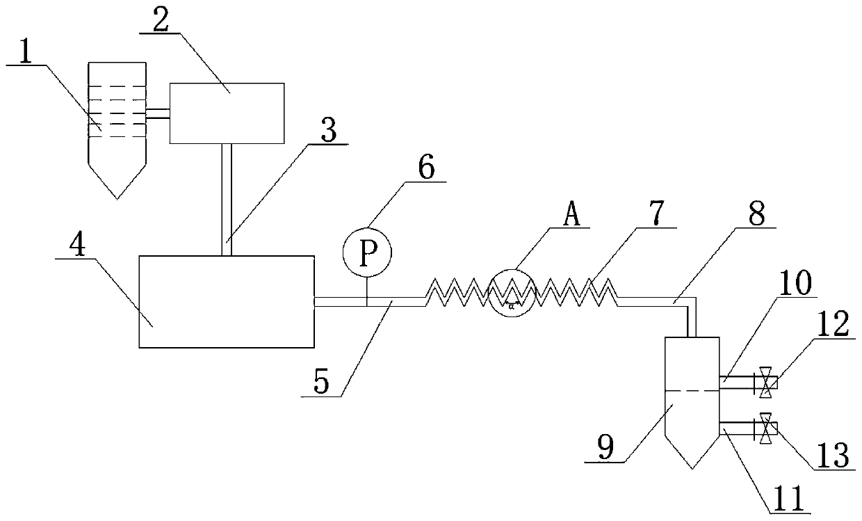
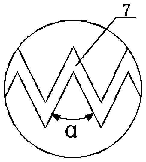
[0035] For a strong turbulent shear microchannel oil-water separation device, see figure 1 , the oily wastewater storage tank 1 is used to place oil and water, start the oily water delivery pump 2 to extract the oily water from the oily wastewater storage tank 1, and enter the pneumatic liquid booster pump 4 through the oily water delivery pipe 3, and the pneumatic liquid booster pump 4 is in the external low-pressure air Driven by the pressure, the oil-water mixture is effectively pressurized and then enters the microchannel 7 through the connecting pipe 5. At the same time, the pressure of the high-pressure liquid is detected by the pressure gauge 6. The high-pressure liquid generates a strong turbulent shear flow field in the microchannel 7, realizing High-efficiency demulsification of the oil-water two-phase, the liquid after demulsification enters the oil-water separation tank 9 through the liquid collection pipe 8 for collection, and what is collected is the liquid in whi...

Embodiment 2

[0038] For a strong turbulent shear microchannel oil-water separation device, see figure 1 , the oily wastewater storage tank 1 is used to store oil and water, start the oily water delivery pump 2 to extract the oily water from the oily wastewater storage tank 1, and enter the pneumatic liquid booster pump 4 through the oily water delivery pipe 3, and the pneumatic liquid booster pump 4 is externally low pressure Driven by the air, the oil-water mixture is effectively pressurized and then enters the microchannel 7 through the connecting pipe 5. At the same time, the pressure of the high-pressure liquid is detected by the pressure gauge 6. The high-pressure liquid generates a strong turbulent shear flow field in the microchannel 7. Realize the high-efficiency demulsification of the two phases of oil and water. The liquid after demulsification enters the oil-water separation box 9 through the liquid collection pipe 8 for collection. The liquid in the upper layer is oil and the lo...


PUM

PropertyMeasurementUnit
Widthaaaaaaaaaa

Abstract

The invention provides a strong turbulence shearing micro-channel oil-water separation device. The device comprises an oily wastewater storage tank (1), an oil-water delivery pump (2), an oil-water delivery pipe (3), a pneumatic liquid booster pump (4), a connecting pipe (5), a micro-channel (7), a liquid collecting pipe (8) and an oil-water separation tank (9) which are sequentially connected inseries, a pressure gauge (6) is arranged on the connecting pipe (5), an oil-phase liquid outlet (10) and a water-phase liquid outlet (11) are respectively formed in the oil-water separation tank (9),an oil-phase switching valve (12) is arranged at the front end of the oil-phase liquid outlet (10), and a water-phase switching valve (13) is arranged at the front end of the water-phase liquid outlet(11). The device disclosed by the invention has the advantages of small equipment investment, high oil-water separation efficiency and capability of realizing continuous operation in the purificationprocess of oily sewage and the like, and can be widely applied to efficient purification treatment on various oily and dusty wastewater.

Description

technical field [0001] The invention relates to a strong turbulent flow shearing microchannel oil-water separation device, which belongs to the field of oily and dusty sewage treatment. Background technique [0002] Liquid-liquid two-phase separation is an important operation unit in the chemical process, and is widely used in various important processes such as crude oil collection, petroleum transportation, reaction separation, extraction, and sewage treatment. Oily sewage mainly comes from petrochemical, iron and steel, coking, gas generation stations, mechanical processing and other industrial sectors, as well as ballast water of large ships. Except for heavy tar, the relative density of oil pollutants in wastewater is generally less than 1 . If the oily sewage is not recycled, it will cause waste on the one hand, and on the other hand, if it is discharged into rivers, lakes or bays, it will cause serious water pollution and affect the survival of aquatic organisms. Whe...

Claims


Application Information

Patent Timeline
IPC IPC(8): B01D17/04
CPCB01D17/044
Inventor 骆培成褚向军刘松琴张袁健李进朱键
Owner SOUTHEAST UNIV
Why Eureka
Try Eureka