
High-damage-threshold liquid crystal optical panel with arbitrary depolarization compensation and exposure device thereof

A high-damage-threshold, liquid crystal optics technology, applied in photoplate-making process exposure devices, microlithography exposure equipment, optics, etc., can solve the problems of low damage threshold, complex structure, and high performance requirements of laser heads, and achieves simple structure, high performance, etc. The effect of precision exposure processing and high aperture ratio

Inactive Publication Date: 2020-06-19
SHANGHAI INST OF OPTICS & FINE MECHANICS CHINESE ACAD OF SCI
View PDF6 Cites 0 Cited by
  • Summary
  • Abstract
  • Description
  • Claims
  • Application Information

AI Technical Summary

Problems solved by technology

Patents CN106451054A and CN107132673A use optically active crystals to combine laser heads to compensate for laser depolarization, and their structures are complex and require high performance of laser heads; patent CN108767644A uses optical addressable liquid crystal light valves to compensate thermally induced depolarization, and its structure is relatively simple. But the damage threshold is low, not suitable for depolarization compensation of high power laser systems

Method used


Image

  • High-damage-threshold liquid crystal optical panel with arbitrary depolarization compensation and exposure device thereof
  • High-damage-threshold liquid crystal optical panel with arbitrary depolarization compensation and exposure device thereof
  • High-damage-threshold liquid crystal optical panel with arbitrary depolarization compensation and exposure device thereof

Examples


Embodiment Construction

[0029] The present invention will be described in detail below in conjunction with the accompanying drawings and specific embodiments. This embodiment is carried out on the premise of the technical solution of the present invention, and detailed implementation and specific operation process are given, but the protection scope of the present invention is not limited to the following embodiments.

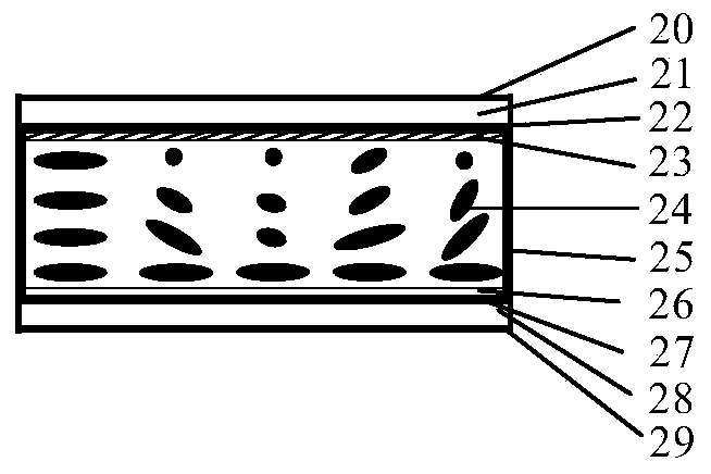
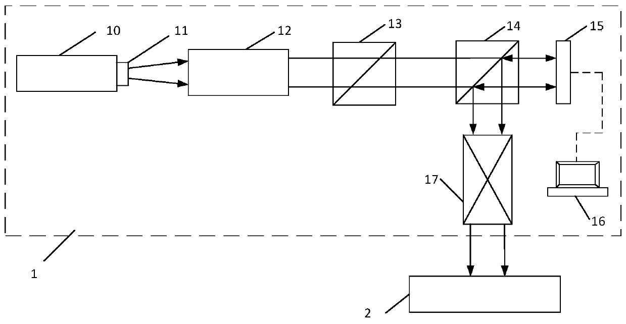
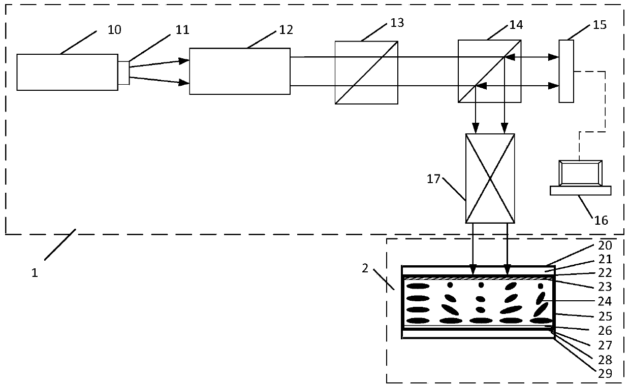
[0030] A high damage threshold liquid crystal optical panel with arbitrary depolarization compensation, which is used for arbitrary polarization state degradation compensation of high-power lasers. The present invention consists of a liquid crystal optical panel 2 and an exposure device 1 for depolarization compensation. Among them, the liquid crystal optical panel 2 is composed of a first dielectric film layer 20, a first glass substrate 21, a second dielectric film layer 22, a light control alignment film layer 23, a liquid crystal layer 24, a spacer frame glue 25, a rubbing alignme...


PUM


Abstract

The invention relates to a high-damage-threshold liquid crystal optical panel with arbitrary depolarization compensation and an exposure device thereof. The high-damage-threshold liquid crystal optical panel with arbitrary depolarization compensation is composed of a composite layer, and a spacer frame adhesive which coats the composite layer. The composite layer comprises a first dielectric filmlayer, a first glass substrate, a second dielectric film layer, a light-operated alignment film layer, a liquid crystal layer, a friction alignment film layer, a third dielectric film layer, a secondglass substrate and a fourth dielectric film layer which are sequentially connected from top to bottom. According to the invention, any polarization distribution gray-scale pattern generated by a reflective electric addressing liquid crystal light valve is inscribed on the light-operated orientation film layer of the liquid crystal optical panel; the high-damage-threshold liquid crystal optical panel with arbitrary polarization distribution has the characteristics of erasable performance, large aperture, high damage threshold, high compensation precision and the like; and the exposure device of the high-damage-threshold liquid crystal optical panel is simple in structure, easy to expand and low in cost.

Description

technical field [0001] The invention belongs to laser beam space shaping, and in particular relates to a high damage threshold liquid crystal optical panel with arbitrary depolarization compensation and an exposure device thereof. The invention is particularly suitable for compensating the problem of thermally induced polarization degradation in a high-power laser 1053nm (but not limited to this wavelength) system and exposing and processing the liquid crystal compensation panel. Background technique [0002] In a high-power laser beam transmission system, a single-polarized laser is generally used as the injection light source. After passing through the gain medium, the polarization characteristics of the laser are difficult to maintain its intrinsic state due to thermal effects, and the polarization state degrades. At present, technologies such as optical active crystal combined laser head and electric / optical addressing liquid crystal light valve are mainly used to compen...

Claims


Application Information

Patent Timeline
IPC IPC(8): G02F1/1333G02F1/1335G02F1/1337G03F7/20
CPCG02F1/1333G02F1/133504G02F1/1337G02F1/133711G03F7/2057G02F1/133507
Inventor 夏刚郭江涛程贺黄大杰范薇
Owner SHANGHAI INST OF OPTICS & FINE MECHANICS CHINESE ACAD OF SCI
Learn More