
Multilayer structure array antenna

An array antenna, multi-layer structure technology, applied in the direction of antenna, antenna coupling, antenna array, etc., can solve problems such as the influence of antenna performance, and achieve the effect of easy processing, simple structure, and improvement of active standing waves

Pending Publication Date: 2020-06-26
NO 54 INST OF CHINA ELECTRONICS SCI & TECH GRP
View PDF0 Cites 2 Cited by
  • Summary
  • Abstract
  • Description
  • Claims
  • Application Information

AI Technical Summary

Problems solved by technology

However, as the cross-sectional size of the patch antenna is reduced, the antenna performance (such as relative bandwidth) will be affected

Method used


Image

  • Multilayer structure array antenna
  • Multilayer structure array antenna
  • Multilayer structure array antenna

Examples


Embodiment Construction

[0023] The present invention will be further described below in conjunction with the accompanying drawings.

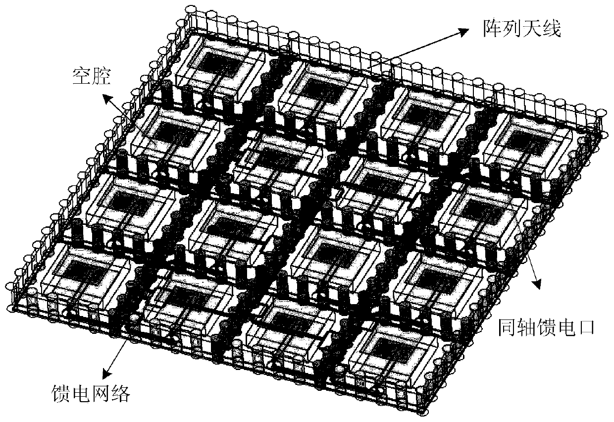
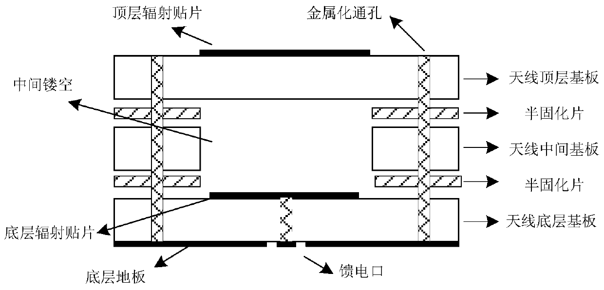
[0024] A multi-layer structure array antenna, the overall structure of which is realized by the multi-layer printed board process. The array antenna includes a plurality of antenna units, and each antenna unit is arranged according to the specified unit spacing. Each antenna unit includes a surface dielectric substrate, a middle layer dielectric substrate, bottom layer dielectric substrate and feed layer dielectric substrate. Among them, the upper surface of the surface dielectric substrate is provided with a metal patch, and the lower surface is exposed without copper cladding; the upper surface and lower surface of the intermediate layer dielectric substrate are exposed without copper cladding, and the middle part of the intermediate dielectric substrate is hollowed out; the upper surface of the bottom dielectric substrate A metal patch is provided, and a metal floor...


PUM


Abstract

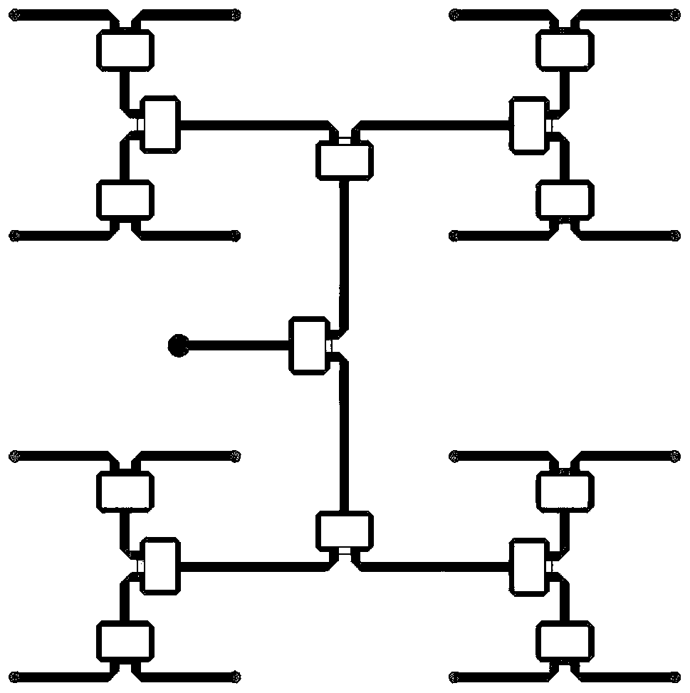
The invention discloses a multilayer structure array antenna, and belongs to the technical field of antennas. The antenna comprises a surface layer substrate, a middle layer substrate, a bottom layersubstrate and a feed network substrate which are arranged from top to bottom; the whole array antenna is divided into a plurality of antenna units. In each antenna unit, a hollow groove is formed in the middle-layer base plate; the upper surface of the surface layer substrate and the upper surface of the bottom layer substrate are respectively provided with an upper layer radiation patch and a lower layer radiation patch at positions corresponding to the hollow grooves, the lower surface of the bottom layer substrate is provided with a metal ground layer, the feed network substrate is providedwith a power division network, and a first metallized through hole used for feeding penetrates through the bottom layer substrate and the feed network substrate. The antenna has the advantages of excellent electrical performance, high integration degree, low profile, simple processing flow, simple design, convenience in use and the like.

Description

technical field [0001] The invention relates to the technical field of antennas, in particular to a multi-layer structure array antenna. Background technique [0002] In recent years, the rapid development of wireless communication technology has put forward higher and higher requirements for antennas. For example, the antenna is required to have the characteristics of high gain, small size, low profile, wide bandwidth, and high directivity. It is usually difficult for a single antenna to meet the requirements, so an array antenna is required. Array antennas are widely used in radar, communication, navigation, measurement and control and other fields. [0003] Microstrip patch antennas have the advantages of compact structure, light weight, low cost, and easy integration. Microstrip antennas are increasingly used in the design of array antennas. However, as the cross-sectional size of the patch antenna is reduced, the antenna performance (such as relative bandwidth) will b...

Claims


Application Information

Patent Timeline
Patent Type & Authority Applications(China)
IPC IPC(8): H01Q1/38H01Q1/48H01Q1/50H01Q1/52H01Q21/00H01Q21/06
CPCH01Q1/38H01Q1/48H01Q1/50H01Q1/523H01Q21/0006H01Q21/065
Inventor 许志涛
Owner NO 54 INST OF CHINA ELECTRONICS SCI & TECH GRP
Learn More