Non-contact slingshot gearbox

A non-contact, gearbox technology, applied in the field of gearboxes, can solve the problems of large operating loss of clutches and gears, difficulty in taking into account speed changes, and aggravating the burden of high speeds, etc., to achieve the effects of increased travel distance, weight reduction, and volume reduction

Active Publication Date: 2020-06-26
厦门翔澧工业设计有限公司
View PDF7 Cites 0 Cited by
  • Summary
  • Abstract
  • Description
  • Claims
  • Application Information

AI Technical Summary

Problems solved by technology

[0004] Moreover, traditional induction motors and engines are opposite to the usage scenarios due to the flywheel effect of the rotor itself. Low-speed torque requires additional weight of the rotor or a flywheel to accumulate enough energy to speed up, but the increased mass imposes a burden on high-speed
On the contrary, a rotor with a lighter weight needs to sacrifice low-speed torque, which causes problems such as difficulty in speeding up. It is difficult to take into account the speed changes required by the application in the design. Reasons such as low speed, poor torque, and reactive power heating need to add reduction gear sets or gearboxes to induction motors and engines, such as Tesla's gear set

Method used


Image

  • Non-contact slingshot gearbox
  • Non-contact slingshot gearbox
  • Non-contact slingshot gearbox

Examples


Embodiment 1

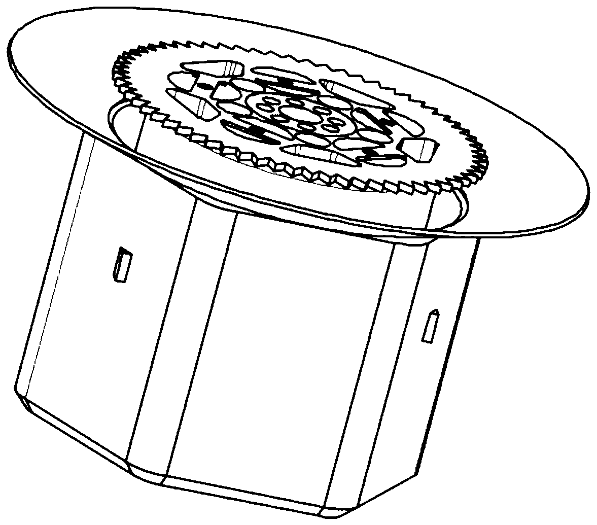
[0045] refer to Figure 1-6 , a non-contact slingshot gearbox, including a housing 1, the casing 1 is provided with a power input end 2 and a power output end 5, and the gearbox includes:

[0046] Several electromagnets 6 are arranged on the power input end 2, and the electromagnet used in the present embodiment is a DC sucker type electromagnet 5030 (commercially available);

[0047] A power supply system, electrically connected to the plurality of electromagnets 6, for supplying power to the plurality of electromagnets 6;

[0048] The magnetic part 4 is used to attract each other with the electromagnet 6 when energized, and the magnetic part 4 includes a silicon steel sheet;

[0049] Output disc 3, the output disc 3 is provided with the magnetic part 4, the output disc 3 is correspondingly arranged inside the input end 2, the output disc 3 is connected to the output end 5, the output disc 3 is used to receive the magnetic field of the electromagnet 6 and follow the rotatio...

Embodiment 2

[0060] This embodiment is basically the same as Embodiment 1, the difference lies in:

[0061] The electromagnet installation groove of the outer input disk 201 and the electromagnet installation groove of the inner input disk 202 are arranged in a misaligned manner.

Embodiment 3

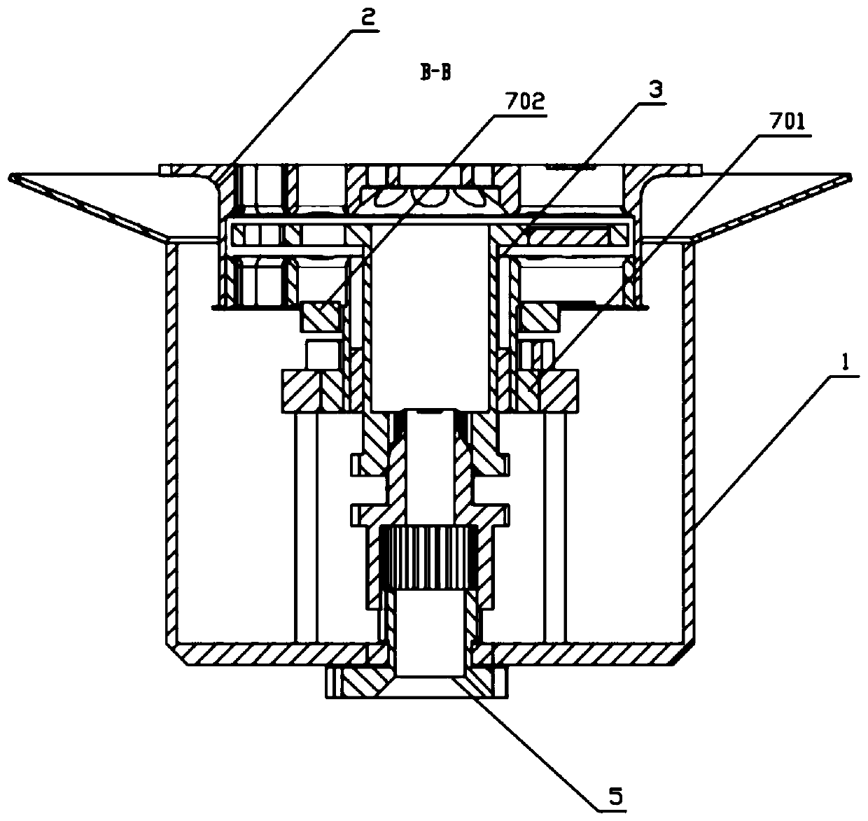
[0063] Use of a contactless slingshot gearbox as an induction motor.

[0064] When the stator 701 conducts alternating current, the frequency and voltage of the alternating current are adjusted, and the rotor 702 and the stator 701 form an induction motor.

[0065] working principle:

[0066] The traditional induction motor uses the principle of electromagnetic induction to generate a rotating magnetic field through the stator current, and interacts with the induced current in the rotor winding to generate electromagnetic torque for energy conversion. In a traditional induction motor, the rotor is inside the stator. In this embodiment, refer to image 3 , the rotor 702 is under the stator 701, the stator 701 generates a changing magnetic field under the drive of alternating current, the rotor 702 cuts the changing magnetic field to generate a changing current, and the changing current inside the rotor 702 further generates a changing magnetic field, the magnetic field of the ...


PUM


Abstract

The invention relates to a non-contact slingshot gearbox. The non-contact slingshot gearbox comprises a shell which is provided with a power input end and a power output end; a plurality of electromagnets arranged at the power input end; a power supply system electrically connected with the plurality of electromagnets and used for supplying power to the plurality of electromagnets; a magnetic partwhich is used for attracting the electrified electromagnets; an output disc which is provided with the magnetic part, is correspondingly arranged in the input end, is connected to the output end, and is used for receiving a magnetic field of the electromagnets and rotates along with the input end; and a control system which is used for receiving a control signal and adjusting the conduction timeduty ratio of the electromagnets so as to change the speed of the output disc.

Description

technical field [0001] The invention relates to the field of gearboxes, in particular to a contactless slingshot gearbox. Background technique [0002] The gearbox is a very important part of the vehicle. It can change the transmission ratio and expand the torque and speed of the driving wheels. With the development of modern technology, the gearbox has also been upgraded. From the initial manual gearbox to the current stepless gearbox, from no synchronizer to synchronizer, the operation is more and more convenient. [0003] Gearboxes require gears and clutches, making such a technology a necessary operating burden; and unavoidable shift delays; power transmission losses; poor reliability; complex electronic control systems; uneven hybrid application; and overall weight affecting distribution heavy problem. The structure of the traditional gearbox is complicated, and the transmission ratio of the gear needs to be changed through the clutch. During this process, the change ...

Claims


Application Information

Patent Timeline
Patent Type & Authority Applications(China)
IPC IPC(8): H02K51/00
CPCH02K51/00
Inventor 赖秉豊
Owner 厦门翔澧工业设计有限公司
Why Eureka
Try Eureka