Valley energy storage water source heat pump energy regulation platform

A water-source heat pump and energy technology, applied in heat pumps, lighting and heating equipment, refrigeration safety arrangements, etc., can solve problems such as insufficient functional design, slow transmission speed, and difficulty in meeting control requirements with manual management methods, so as to improve the level of automation control, The effect of improving control efficiency

Pending Publication Date: 2020-06-30
CECEP CHANGZHOU INST FOR ENERGY SAVING
View PDF2 Cites 0 Cited by
  • Summary
  • Abstract
  • Description
  • Claims
  • Application Information

AI Technical Summary

Problems solved by technology

[0003] Water source heat pump is a complex system coupled with each other. Traditional manual management methods are difficult to meet the control requirements. Therefore, professional software or energy management and control platforms are getting more and more attention. For example, the patent application number CN201620413618. Heat pump system energy management platform" patent application number CN201720739235.1 announced "air-cooled heat pump automatic energy management platform" etc.
However, it should be pointed out that the patent of "an energy management platform for ground source heat pump system" has insufficient functional design (for example, the alarm design is not considered), different serial port connections are used between different collection systems, and the transmission speed is slow; The automatic energy management platform for cold and heat pumps failed to fully consider the characteristics of energy peaks and valleys in application scenarios, and targeted development of energy storage control strategies and other issues

Method used


Image

  • Valley energy storage water source heat pump energy regulation platform
  • Valley energy storage water source heat pump energy regulation platform
  • Valley energy storage water source heat pump energy regulation platform

Examples


Embodiment Construction

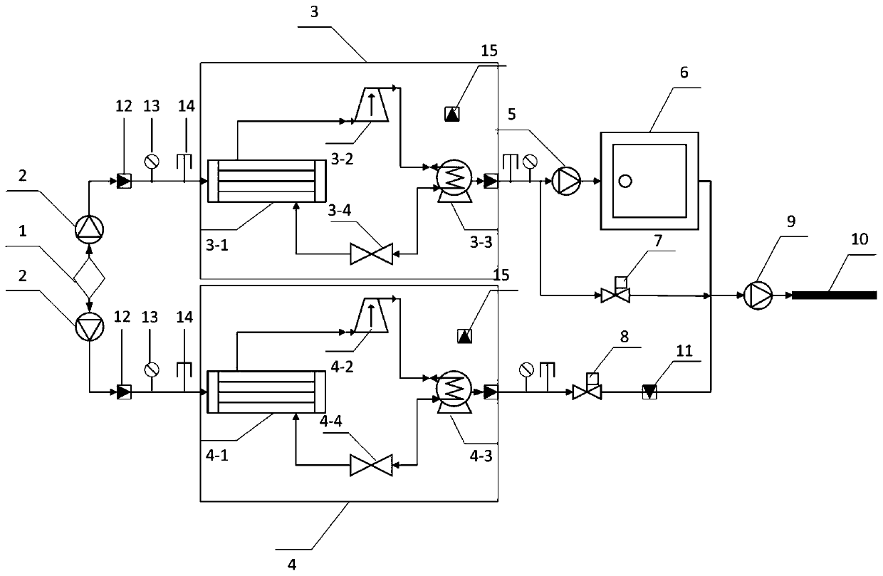
[0015] Such as figure 1 , 2 As shown, a valley electricity energy storage water source heat pump energy control platform is characterized in that it includes a plurality of heat pump units, and the heat pump unit 3 consists of a compressor 3-2, a condenser 3-3, and a throttle valve 3-3. 4. Evaporator 1 3-1 is connected sequentially, and heat pump unit 2 4 is composed of compressor 2 4-2, condenser 2 4-3, throttle valve 2 4-4, and evaporator 4-1 in sequence , water intake pump 2 pumps source water 1 into evaporator 1 3-1 of heat pump unit 1 3 and evaporator 2 4-1 of heat pump unit 2 4 respectively, heat pump unit 1 3 is connected to water pump 5 and electric valve 1 7, heat pump unit Two 4 is connected to the electric valve two 8, the water pump 5 is connected to the energy storage pool 6, the energy storage pool 6 is connected to the circulation pump 9, and the circulation pump 9 is connected to the energy supply pipe network 10, and the electric valve one 7 is closed during ...


PUM


Abstract

The invention discloses an energy regulation and control platform of a valley electric energy storage water source heat pump, which comprises a plurality of heat pump units, wherein the front ends ofthe heat pump units are all connected with a flowmeter, a pressure sensor, a temperature sensor and an intelligent electric meter; The energy meter, flowmeter, intelligent electric meter and water pump frequency converter are in communication connection with the control cabinet through Modbus communication protocol; the pressure sensor, temperature sensor, electric valve I and electric valve II are in communication connection with the control cabinet through analog signals; the network phone and network camera are in communication connection with the switch through network; the switch is connected with the industrial computer and monitoring center through network cables. According to the invention, an energy regulation and control platform of the valley electric energy storage water sourceheat pump is constructed, the automatic control level is improved, and the system automatically judges the operation strategy of the peak and valley electric periods through the control strategy, sothat the host computer is always kept in the best performance state, and peak shaving and valley filling can be realized, thereby saving energy and reducing consumption.

Description

technical field [0001] The invention relates to the technical field of HVAC automation control, in particular to an energy regulation platform for valley electricity storage water source heat pumps. Background technique [0002] Water source heat pump refers to the transfer of low-level heat energy to high-level heat energy by inputting a small amount of high-grade energy (such as electric energy) and using the solar energy resources stored in the earth's water as a cold and heat source. In summer, the temperature of the water source is low, and the heat in the building can be extracted and released into the water body through the heat pump unit to achieve the purpose of cooling; in winter, the temperature of the water source is high, and the heat pump unit can extract the heat from the water body and transport it to the building to achieve the purpose of heating. Water source heat pumps have the advantages of energy saving and environmental protection compared with traditi...

Claims


Application Information

Patent Timeline
IPC IPC(8): F25B49/02F25B30/02
CPCF25B30/02F25B49/02
Inventor 杜玉吉张晓灵梁安娜唐蓓姜丹丹王辉
Owner CECEP CHANGZHOU INST FOR ENERGY SAVING
Why Eureka
Try Eureka